
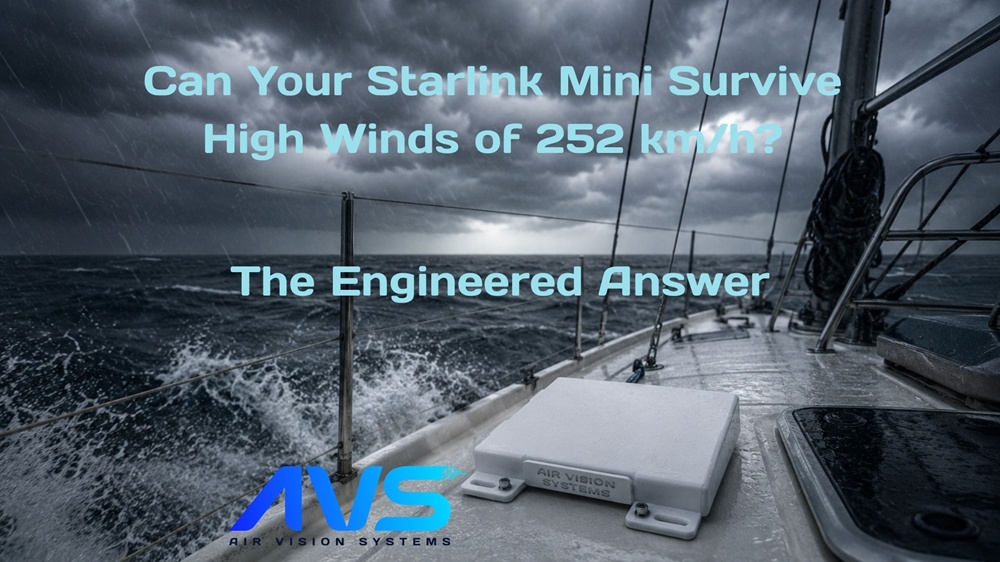
Based on engineering analysis commissioned by Air Vision Systems (AVS) | NZ, AU and Global
When Cyclone Chido made landfall over Mayotte in December 2024, it was the most powerful storm to hit the French Indian Ocean territory in nearly 90 years. Wind speeds exceeded 220 km/h. Infrastructure was devastated. For sailors, overlanders, caravan travellers and remote workers caught in conditions like that, reliable communications isn’t a convenience. It’s the difference between safety and serious danger. This post covers the Starlink Mini mount wind rating in detail, from the CFD pressure analysis through to the FEA fatigue testing that proved it out.
The Starlink Mini has become the go-to dish for exactly these people, compact enough for a yacht mast, a 4×4 roof rack, or a caravan A-frame, but capable enough to keep you connected in the most remote corners of the world. The question is whether the mount holding it in place can handle what those environments throw at it.
The Air Vision Systems Starlink Mini Mount was designed with that question in mind. Our engineering brief started with the highest wind speed ever recorded in Wellington, New Zealand over the last 100 years, 248 km/h, and was then extrapolated to 252 km/h, the sustained wind speed threshold for a Category 5 hurricane. We then commissioned a full Computational Fluid Dynamics (CFD) and Finite Element Analysis (FEA) structural simulation to prove the mount could survive both. This post walks you through what was tested, what the numbers mean, and why it matters for anyone running Starlink in a serious environment.
What We Tested and Why
The Air Vision Systems Starlink Mini Mount is built from white powder-coated marine-grade aluminium with a high-quality polycarbonate top cover. It’s designed for the kinds of installs where conditions can turn serious: yacht masts, 4×4 roof racks, caravan A-frames, motorhomes, camper vans, expedition vehicles and work boats. In those environments, the mount isn’t just holding a dish in place on a calm day. It needs to hold through whatever the weather throws at it, mile after mile and storm after storm.
To back that up with hard data, we commissioned a two-stage engineering simulation. First, a Computational Fluid Dynamics (CFD) analysis to calculate the pressure that Category 5 hurricane winds would place on the cover surface. Second, a Finite Element Analysis (FEA) to test whether the structure could withstand that pressure repeatedly, across a billion load cycles. The goal was straightforward: find any weak points before the weather does.
How Wind Load Was Calculated
The wind load calculation started with real-world data. Wellington, New Zealand holds one of the highest recorded wind speeds of any city on earth, and that recorded peak of 248 km/h became the baseline for our engineering brief. From there, the simulation was extrapolated to 252 km/h, the sustained wind speed threshold for a Category 5 hurricane on the Saffir-Simpson scale, to ensure the mount was tested against the most extreme benchmark possible.
A Computational Fluid Dynamics (CFD) simulation was run with airflow directed perpendicularly onto the full face of the dish cover, the worst-case scenario for wind loading. This identified the stagnation point at the centre of the cover, where oncoming airflow drops to zero velocity and pressure peaks at its highest. The maximum stagnation pressure recorded was 2,834.6 Pa, which was then applied uniformly across the entire cover surface for the structural analysis rather than just at the stagnation point. Applying it uniformly is a deliberately conservative approach, ensuring the results reflect worst-case conditions rather than a more favourable real-world pressure distribution.
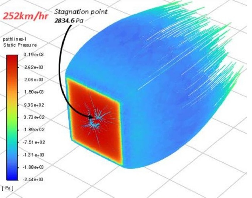
CFD simulation: stagnation pressure at 2,834.6 Pa at 252 km/h wind speed
What the Structural Analysis Revealed
With the wind pressure load established, it was applied to a full structural model of the Mini mount assembly in the Finite Element Analysis (FEA) simulation. To identify the most critical stress points, the model was run under fully reversed fatigue loading, meaning the load cycles repeatedly in both directions, which represents the harshest possible fatigue scenario. This is the kind of loading a mount on a yacht or a 4×4 experiences in reality: not one big hit, but thousands of repeated stress cycles over years of use.
The analysis used the Soderberg method to calculate the results, widely regarded as the most conservative approach in fatigue engineering, factoring in both alternating stress and mean stress to produce a rigorous assessment of long-term durability.
The results were excellent. The mount passed comfortably across all three foundation types tested, returning a minimum fatigue safety factor of above 10 in every case, across one billion fully reversed load cycles at Category 5 wind pressure. In plain terms: at 252 km/h wind loading, the structure has more than ten times the strength required to avoid fatigue failure under continuous repeated loading.
As with the Gen 3 mount, the highest stress in the assembly was concentrated in the aluminium base bracket, specifically in the spring-action holding sections that flex slightly under load and absorb stress away from the bolts and the polycarbonate cover. The design channels stress into the areas built to handle it, protecting the rest of the assembly.
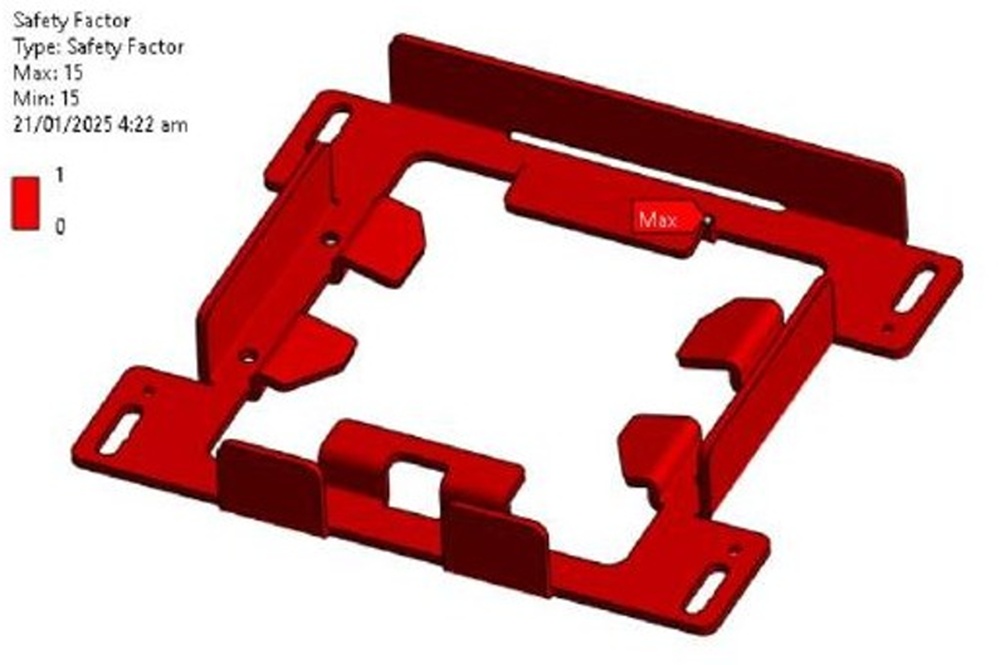
Fatigue factor of safety result: minimum FOS above 10 across 1 billion load cycles (Soderberg method)
Engineering Note: How the Wind Load Was Calculated
The CFD simulation used an airflow velocity of 248 km/h, the highest wind speed recorded in Wellington, New Zealand over the last 100 years, directed perpendicularly onto the full dish cover surface, then extrapolated to 252 km/h for Category 5 hurricane conditions. This is the worst-case loading scenario. The maximum stagnation pressure of 2,834.6 Pa was then applied uniformly across the entire cover face for the structural analysis, a deliberately conservative approach that exceeds real-world pressure distribution. The fatigue analysis used the Soderberg method, the most conservative calculation standard in fatigue engineering, and tested to one billion fully reversed load cycles. Minimum safety factor recorded: above 10 across all three foundation types tested.
Read the report here (redacted): Engineering Report Summary
The full unredacted report is available under NDA to distributors, wholesale partners, Starlink installers, commercial operators, infrastructure and telecommunications providers, and insurers or risk assessors with a legitimate requirement. Contact us to request access.
Does the Mounting Surface Matter?
For anyone installing a Starlink Mini on a boat, a 4×4, a caravan or a motorhome, the mounting surface varies considerably. A fibreglass boat deck, a steel roof rack, a timber caravan frame, a concrete pad at a remote work site, the base material changes depending on the application. So the simulation tested all three of the most common real-world foundation types: plywood, steel, and concrete.
The short answer is that all three pass. Comfortably.
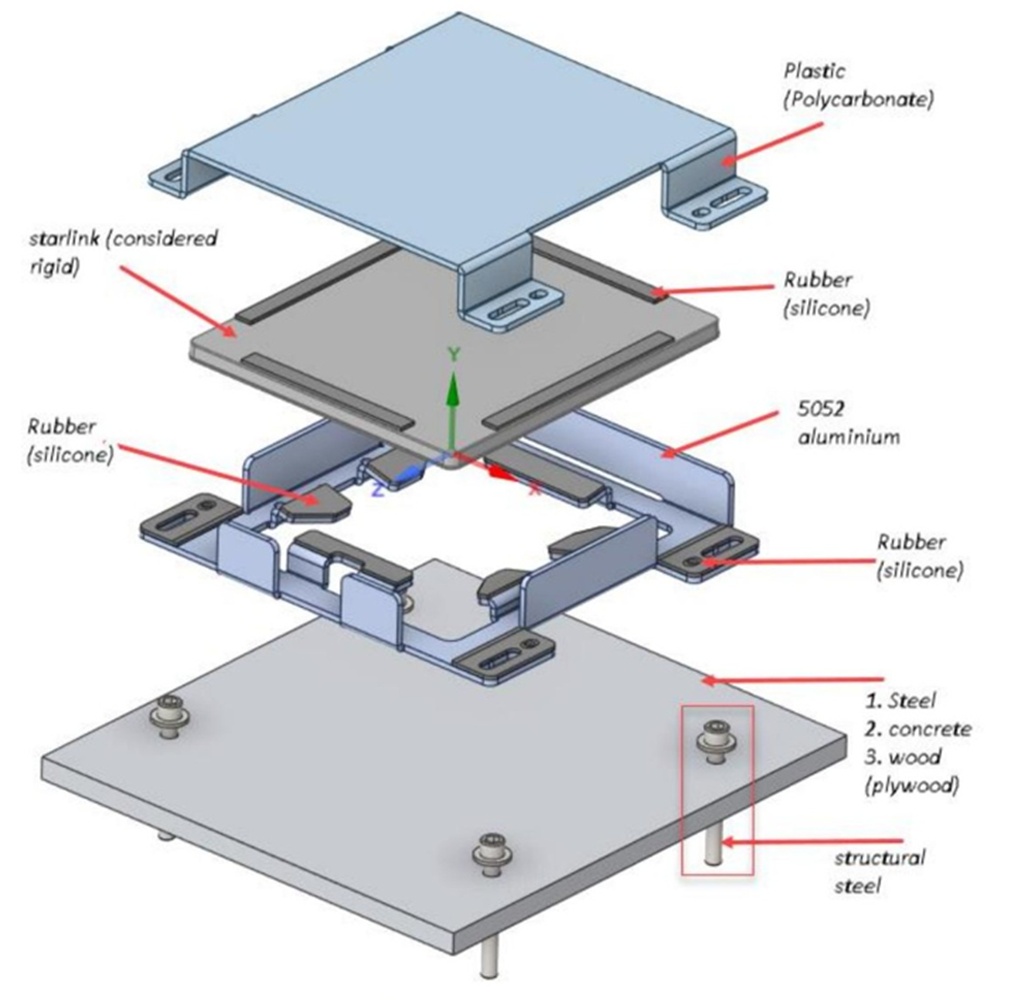
Air Vision Systems Starlink Mini mount assembly: polycarbonate cover, aluminium base, silicone pads, steel fixings
Both the plywood and steel foundations returned a minimum fatigue safety factor of above 10. Concrete performed comparably to steel, with a nearly identical result. Across all three cases the stress distribution remained even, the polycarbonate top cover showed no meaningful deformation at a maximum of 1.9 mm under full Category 5 load, well within acceptable limits that have no impact on structural integrity, and the aluminium bracket tips moved less than 1 mm in every case.
For a product designed to be used across such a wide range of mobile and fixed installations, that consistency matters. Whether the Air Vision Systems Starlink Mini Mount is secured to a timber deck, a steel frame, or a concrete surface, the engineering outcome is the same. The mount holds. The Starlink stays connected.
What a Safety Factor of 10+ Actually Means
Safety factor is an engineering term that doesn’t always land well outside technical circles, so it’s worth explaining what it actually means in plain language.
A safety factor of 1 means a structure is right at its limit: any additional load and it fails. A safety factor of 2 means it can handle twice the design load before failure. A safety factor of 10 means the structure would need to experience ten times the applied load before reaching its fatigue limit. In this case, that applied load is already Category 5 hurricane wind pressure. So the mount would need to be subjected to the equivalent of ten Category 5 hurricanes simultaneously before the engineering model predicts fatigue failure.
For context, structural engineers typically consider a safety factor of 2 to 3 acceptable for most applications. Safety factors above 5 are considered highly conservative. The Air Vision Systems Starlink Mini Mount exceeds that benchmark by a factor of two, across every foundation type tested, using the most conservative fatigue calculation method available.
This matters especially for mobile installs. A yacht in heavy seas, a 4×4 on a corrugated outback track, a caravan on a rough gravel road, these environments don’t just expose a mount to wind. They expose it to repeated vibration, impact loading and dynamic stress cycles over thousands of kilometres and years of use. Engineering to one billion fully reversed load cycles at Category 5 pressure, with a safety factor above 10, means the Air Vision Systems Starlink Mini Mount is built to go wherever the Starlink Mini goes, and keep working when it gets there.
Built for wherever the Starlink Mini goesThe Air Vision Systems Starlink Mini Mount is engineered and tested to Category 5 hurricane wind speeds, not as a marketing claim, but as a verified engineering outcome. Whether you’re rigging it to a yacht mast, bolting it to a 4×4 roof rack, or mounting it on a caravan A-frame, this is the mount built to keep your Starlink Mini connected when the conditions turn serious.
Frequently Asked Questions
Will the polycarbonate cover affect my Starlink Mini signal?
Not at all. The polycarbonate top cover is fully signal-transparent and has no impact on Starlink Mini performance. You get complete top protection from the elements without any compromise to your connection.
What is the Starlink Mini Mount wind rating?
The mount was tested to 252 km/h, the sustained wind speed threshold for a Category 5 hurricane on the Saffir-Simpson scale. The engineering brief started with the highest wind speed ever recorded in Wellington, New Zealand over the last 100 years (248 km/h) and was then extrapolated to 252 km/h for the structural simulation. This was validated using a full Computational Fluid Dynamics (CFD) and Finite Element Analysis (FEA) engineering simulation.
Can the mount be used on a boat or yacht in cyclone-prone waters?
Yes. The mount is constructed from white powder-coated marine-grade aluminium specifically to handle saltwater and harsh marine environments. Combined with the Category 5 wind load testing and a safety factor of above 10, it is well suited to boat, yacht and coastal installs in cyclone and hurricane-prone regions worldwide.
How does a safety factor of 10+ compare to standard engineering requirements?
Structural engineers typically consider a safety factor of 2 to 3 acceptable for most applications, and anything above 5 is regarded as highly conservative. The Air Vision Systems Starlink Mini Mount returned a minimum safety factor of above 10 across all three foundation types tested, using the most conservative fatigue calculation method available. That means the mount has more than ten times the strength required to avoid fatigue failure at Category 5 wind loading.
Is the Air Vision Systems Starlink Mini Mount suitable for 4×4 and overland vehicle installs?
Yes. The mount is compact, lightweight at 1.73 kg, and built from marine-grade aluminium to handle the vibration, dust and dynamic loading that off-road and overland use demands. It’s compatible with Starlink Mini and designed for exactly the kind of remote and mobile installs where 4x4s and expedition vehicles operate.
Where can I read the full engineering report?
A redacted summary of the engineering report is available to read here. The full unredacted report is available under NDA to distributors, wholesale partners, Starlink installers, commercial operators, infrastructure and telecommunications providers, and insurers or risk assessors with a legitimate requirement. Contact us to request access.
What the Engineering Tells Us
Most mounting products are designed to look good in product photos. The Air Vision Systems Starlink Mini Mount was designed to survive the kind of conditions that Cyclone Chido delivered to Mayotte.
That meant starting with the hardest real-world data available, the highest wind speeds ever recorded in Wellington over the last 100 years, and engineering upward from there to Category 5 hurricane conditions. It meant commissioning independent CFD and FEA structural simulations, testing to one billion fatigue cycles, using the most conservative calculation methods available, and validating the results across three different foundation types. It meant not stopping until the numbers said the mount would hold.
The result is a safety factor of above 10 at 252 km/h. On plywood, steel, and concrete. With the polycarbonate top cover signal-transparent and protecting the dish throughout.
If you’re running Starlink Mini somewhere the weather can turn serious, a yacht in cyclone-prone waters, a 4×4 in remote terrain, a caravan on the road, a fishing vessel offshore, the Air Vision Systems Starlink Mini Mount is the only Starlink Mini mount with the engineering data to back up every claim we make.
View the Air Vision Systems Starlink Mini Mount
Want to dig into the numbers yourself? The redacted engineering report summary is available to read here.