
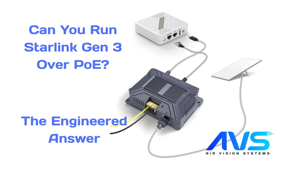
Based on engineering analysis commissioned by Air Vision Systems (AVS) | NZ and AU
Starlink Gen 3 PoE (Power over Ethernet) installs are becoming the standard choice for commercial and residential structured cabling environments, but getting the setup right takes more than plugging in a cable. If you’re installing Starlink Gen 3 in a building, office, or commercial premises, or if you’re a network installer who wants a clean, single-cable solution to the roof, PoE is the natural choice. But Starlink Gen 3 is a high-power device, and not all PoE implementations are equal. Getting the cable category, conductor gauge, voltage, and run length right is the difference between a compliant install and one that causes intermittent dropouts or fails to power the terminal at all.
The good news is that Starlink Gen 3 is fully compatible with PoE-based power delivery, provided the right infrastructure is in place. At 57V over Cat6A 24 AWG cabling, the Gen 3 remains compliant up to 100 metres, consistent with IEEE 802.3bt and standard structured cabling channel length limits. At 48V the limit comes down to around 90 metres, still more than enough for most building installs.
This post is based on a formal electrical engineering report commissioned by Air Vision Systems, covering power delivery compliance for Starlink Gen 3 across PoE voltages, cable types, and run lengths. We’ve translated the technical findings into plain English for installers and commercial buyers planning structured cabling deployments.
What PoE Actually Means for Starlink Gen 3
Power over Ethernet is a technology that delivers DC power alongside data over standard twisted-pair cabling. For Starlink Gen 3, it means you can run a single Cat6A cable from a PoE injector or switch at the distribution point to the dish location, carrying both the internet connection and the power to run the terminal. No separate power cable to the roof, no additional conduit runs, no AC outlet required at the install point.
The Starlink Gen 3 draws between 75 and 100 watts continuously. At 57V, the native output voltage of the official Starlink AC adapter, that equates to approximately 1.32 to 1.75 amps of current. At 48V, the current rises to around 2.08 amps at 100W load. These are the two PoE voltage levels relevant to Gen 3 installs, and the difference between them has a direct impact on how far you can run the cable.
For PoE power delivery, the engineering report uses four-pair cabling in the IEEE 802.3bt configuration: two pairs carrying positive and two pairs carrying negative. This parallel arrangement halves the effective loop resistance compared to a single-pair run, which is what allows compliant cable runs of 90 to 100 metres at these power levels.
57V vs 48V: Which PoE Voltage Should You Use?
The choice between 57V and 48V distribution is the single most important decision in a Starlink Gen 3 PoE install. Both are viable, but they have different cable length limits and different tolerance for cable gauge, and the wrong combination can push a longer run outside compliance before you realise it.
57V, the recommended standard
At 57V over Cat6A 24 AWG, the engineering report confirms compliance up to 100 metres, the full standard structured cabling channel length under IEEE 802.3bt. Voltage drop at 100 metres is well within the 10% compliance threshold, leaving margin for connector resistance and cable aging. At 24 AWG, the full 100 metre channel is achievable. At 26 AWG, the engineering calculations put the maximum compliant length at approximately 79 metres at 57V, still useful for most installations, but confirm your gauge before specifying longer runs.
For new installs where you have a choice, 57V is the right answer. It aligns with the Gen 3’s native operating voltage, gives you the full 100 metre channel, and provides the most comfortable compliance margin across the range of cable lengths you’re likely to encounter in a real building.
48V, a viable alternative with tighter limits
At 48V, 24 AWG Cat6A remains compliant up to approximately 90 metres, still more than sufficient for most building installs. At 26 AWG, the compliance margin is tighter and cable gauge becomes more critical. At 46 metres with 26 AWG Cat6A, the delivered voltage is 44.9V, a 6.5% drop, which sits within the 90% compliance threshold confirmed by the engineering report.
The practical safe working limit for 26 AWG at 48V is approximately 70 metres, beyond which the margin narrows further and voltage drop can push the run outside compliance. If you’re working with 26 AWG cable at 48V, keep runs within that limit and verify load voltage at commissioning. This matters most as run length approaches the ceiling, where connector resistance and cable ageing can erode the remaining margin. If you’re unsure of the gauge in an existing installation, measure the resistance before commissioning rather than assuming compliance.
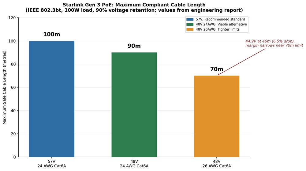
Figure 1: Maximum compliant cable lengths for Starlink Gen 3 PoE. 57V 24 AWG: 100m. 48V 24 AWG: 90m. 48V 26 AWG: 70m practical limit, with 44.9V delivered at 46m (6.5% drop, within the 90% compliance threshold). All values directly from the engineering report.
Cat5e vs Cat6A: Does Cable Category Matter?
This is one of the most common questions in structured cabling installs, and the engineering report gives a clear answer: for DC power delivery purposes, the determining factor is conductor gauge, not cable category.
Cat5e and Cat6A cables with the same AWG conductors produce identical voltage drop results. At 57V, Cat5e 24 AWG is compliant up to 100 metres, the same as Cat6A 24 AWG. At 48V, Cat5e 24 AWG is compliant up to approximately 90 metres, again matching Cat6A performance at the same gauge.
So why does the report recommend Cat6A over Cat5e for Starlink Gen 3 installs? Three reasons, none of which are electrical:
• Mechanical Robustness: Cat6A cable is physically larger and more durable, with better crush resistance and improved tolerance for the bending radii and installation forces typical of commercial cable pulls.
• Termination Quality: Cat6A connectors and patch panels are engineered to tighter tolerances, which means lower and more consistent contact resistance at each termination point.
• Future Proofing: Cat6A supports 10 Gigabit Ethernet to 100 metres where Cat5e is limited to 1 Gigabit. Installing Cat6A once is cheaper than retrofitting later.
The bottom line: if you’re installing new cabling, use Cat6A. If you’re working with an existing Cat5e 24 AWG installation, it’s electrically compliant for Starlink Gen 3 PoE, but verify the gauge before assuming.
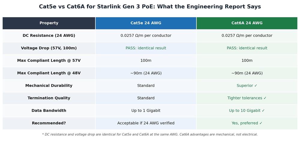
Figure 2: Cat5e vs Cat6A for Starlink Gen 3 PoE. Electrically identical at 24 AWG. Cat6A is recommended for mechanical robustness, termination quality, and future-proofing.
PoE Injectors, Splitters, and System Architecture
Understanding the cable compliance is only part of a structured Starlink Gen 3 PoE install. The components that sit at each end of the cable run matter just as much, and getting the architecture right determines whether the whole system performs as the engineering calculations predict.
The basic PoE architecture
A standard Starlink Gen 3 PoE install follows a straightforward path: a 12V battery or DC source feeds a step-up converter, which outputs 57V DC into a PoE injector. The injector combines the power with the data signal and pushes both down the Cat6A backbone to the dish location. At the dish end, a PoE splitter separates power and data, delivering regulated DC to the Gen 3 terminal and passing the data signal through to the router.
Converter and injector specifications
Where a 12V source is used, the engineering report recommends a 12V to 57V converter rated at 3A output (171W). At 12V input, the converter draws approximately 15 amps, so the input side must use at least 2.5mm² (AWG 14) cabling for runs up to 2 metres, stepping up to 4mm² (AWG 12 or AWG 10) beyond that, and must be protected with a 20 amp fuse fitted close to the battery.
Grounding and bonding
In a structured cabling environment, proper grounding and bonding of all DC cabling is a compliance requirement, not an optional extra. The engineering report specifically references TIA-568 wiring practices for PoE over Cat6A cabling. In commercial installs, this means ensuring the PoE infrastructure is bonded to the building earth and that all metallic cable management is continuously bonded throughout.
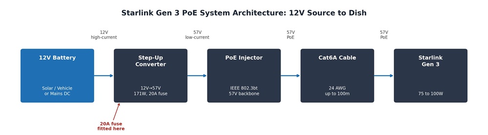
Figure 3: Starlink Gen 3 PoE system architecture from a 12V source. The 20A fuse fits close to the battery, the step-up converter outputs 57V into the PoE injector, and Cat6A carries power and data to the dish.
Compliance, Derating, and Real-World Installation Margins
The cable length limits in the engineering report are calculated from first principles using standard copper resistance values at 25°C and a 10% maximum voltage drop threshold. They represent the maximum compliant lengths under defined conditions, not targets to aim for. In a real building install, several factors reduce the available margin.
Temperature: Copper conductor resistance increases with temperature at approximately 0.4% per degree Celsius. In a roof space or conduit in direct sun, cable temperatures can significantly exceed the 25°C reference. The engineering report recommends applying a 10 to 15% derating factor to calculated maximum lengths.
Connector Resistance: Every termination point in the cable run adds a small amount of resistance. A poorly terminated RJ45 or a damaged patch panel port can add meaningful resistance to the loop. The 90% voltage retention criterion provides some margin for typical connector losses, but it assumes competent termination practice throughout.
Cable Aging: Conductor resistance increases slightly over time as connections oxidise. The derating recommendation accounts for this and ensures the installation remains compliant over its service life, not just at commissioning.
Practical Guidance for Installers: measure end-to-end resistance before commissioning, verify load voltage at the terminal under full operating conditions, and log the results. A compliant installation can be documented and signed off with confidence. One that’s commissioning at the edge of the calculated limit without measurement data is a callback waiting to happen.
Did You Know?
At 48V with 26 AWG Cat6A cable, voltage drop increases quickly with distance. At 46 metres, the delivered voltage is 44.9V, a 6.5% drop, still within the 90% compliance threshold. But push much further and 26 AWG runs out of margin fast: the practical safe limit is approximately 70 metres before the drop becomes too large to guarantee reliable operation. This is exactly why cable gauge and voltage selection matter in a structured Starlink install, and why the engineering report recommends 57V over 24 AWG Cat6A as the standard configuration.
Air Vision Systems stocks DC-DC step-up converters, PoE injectors, and structured cabling specified to the exact compliance requirements covered in this post. Browse the ranges below:
Air Vision Systems Power Supplies: 12V to 57V step-up converters for Starlink Gen 3
Air Vision Systems PoE Injectors: PoE injection hardware for structured Cat6A installs
Air Vision Systems Cables: Cat6A and DC cables manufactured to compliance specifications
Air Vision Systems Smart Cable Calculator: check your specific run length and gauge before you order
Frequently Asked Questions
Can Starlink Gen 3 be powered over a standard PoE network switch?
It depends on the switch’s PoE standard and power budget. Starlink Gen 3 draws up to 100W continuously, which requires IEEE 802.3bt (PoE++) rated equipment. Standard 802.3af (15.4W) and 802.3at (30W) PoE switches do not provide sufficient power. Always verify your switch or injector is rated for at least 100W per port before commissioning.
What is the maximum cable length for Starlink Gen 3 over PoE?
At 57V over Cat6A 24 AWG, the engineering report confirms compliance up to 100 metres, the full standard structured cabling channel length under IEEE 802.3bt. At 48V, compliance extends to approximately 90 metres on 24 AWG Cat6A. Runs beyond these limits fall outside the 10% voltage drop compliance threshold.
Does it matter whether I use Cat5e or Cat6A for a Starlink Gen 3 PoE install?
For DC power compliance, Cat5e and Cat6A with the same 24 AWG conductors perform identically. Cat6A is recommended for new installs due to better mechanical durability, termination quality, and future-proofing for 10 Gigabit Ethernet. If working with an existing Cat5e 24 AWG installation, verify the conductor gauge before assuming compliance.
Why does cable gauge matter more than cable category for PoE power delivery?
Voltage drop is determined by conductor resistance, which is a function of wire cross-section, AWG gauge, not the cable category label. A Cat6A cable with 26 AWG conductors will produce more voltage drop per metre than a Cat5e cable with 24 AWG conductors. Always confirm the AWG gauge of the cable being used, not just the category rating.
What happens if the voltage at the Starlink Gen 3 terminal drops below the compliance threshold?
The engineering report defines compliance as the terminal receiving at least 90% of the source voltage, no less than 51.3V at a 57V supply, or 43.2V at 48V. Below these levels the terminal may intermittently power on but operation becomes unstable. In a commercial install, this typically presents as unexplained dropouts or connection instability.
Not Sure Which Cable to Use? Try the Air Vision Systems Smart Cable Calculator
If you want to verify your specific cable run before ordering, different lengths, gauges, or DC voltages, the Air Vision Systems Smart Cable Calculator does the hard work for you. It’s built on the same engineering methodology behind this report.
Try it here: Air Vision Systems Smart Cable Calculator
What the Engineering Tells Us
Starlink Gen 3 over PoE is a clean, professional installation solution for commercial and residential structured cabling environments, provided the infrastructure is specified correctly. Use 57V over Cat6A 24 AWG for the most compliant and future-proof deployment, with runs up to 100 metres covered under IEEE 802.3bt. If your infrastructure runs at 48V, stick to 24 AWG Cat6A and keep runs within 90 metres. At 48V, 26 AWG is compliant to approximately 70 metres, but the margin is tight. Beyond that point, voltage drop pushes the run outside compliance, and the failure mode is intermittent rather than an obvious hard stop.
Apply a 10 to 15% derating factor to calculated maximums, verify load voltage at the terminal under full operating conditions before sign-off, and document the results. A Starlink Gen 3 PoE install done properly is a reliable, low-maintenance solution. One done on assumptions is a callback.
The findings in this post come from a formal electrical engineering report commissioned by Air Vision Systems, the same methodology behind the full Air Vision Systems Starlink compliance series, consistent, traceable, and built for use in compliance documentation and installation specifications.
Ready to spec your Starlink Gen 3 PoE install?
Browse Air Vision Systems PoE Injectors, Air Vision Systems Power Supplies, or find the right cabling at Air Vision Systems Cables.