
Based on engineering analysis commissioned by Air Vision Systems | NZ, AU and Global
It is one of the most common questions in any Starlink install: how long should my Starlink pole be? Most people pick a length based on what clears the roofline or what is available at the hardware store. But according to structural engineering analysis commissioned by Air Vision Systems, pole length is the single biggest variable in how your mount performs under wind load, and there is a clear, engineered answer to what is safe and what isn’t.
This post is based on CFD and FEA engineering analysis prepared for Air Vision Systems, covering Starlink Gen 3 mounts tested against wind conditions up to 248 km/h across four pole length configurations from 300 mm to 3,000 mm. The findings give installers, property owners, and specifiers a practical, evidence-based framework for getting pole length right, whether you are doing a sheltered suburban rooftop or an exposed coastal site.
Why Pole Length Is the Most Important Decision in Your Starlink Install
Most of the attention in a Starlink installation goes on the hardware, the mount, the dish, the cabling. Pole length tends to be treated as an afterthought. The structural engineering analysis commissioned by Air Vision Systems shows that is the wrong way to think about it.
Pole length determines the bending moment your mount has to resist under wind load. A longer pole acts as a lever arm. The further the dish sits from the base of the mount, the greater the rotational force that wind pressure applies at the fixing point. That relationship is not linear. As pole length increases, the bending moment at the base grows significantly, and the structural demands on the pole, bracket, and fasteners increase with it.
The FEA testing in this analysis modelled the full range, from a minimum pole length of 300 mm to a maximum of 3,000 mm, all under the same 248 km/h wind input. The difference in outcomes between the two extremes is stark: 18.1 mm of total deformation at 300 mm, versus maximum equivalent stress of 14,589 MPa at 3,000 mm. Same mount hardware, same wind conditions, dramatically different structural result. The only variable is pole length.
That is why getting pole length right is the most important single decision in a Starlink install. Everything else, wall thickness, fastener specification, bracket orientation, is secondary to keeping the pole as short as the installation allows.
What the Engineering Testing Found at Each Pole Length
The finite element analysis tested four load cases across the pole length range, all subjected to the same worst-case wind input of 248 km/h. The results give a clear picture of how structural performance changes as pole length increases.
300 mm pole, minimum length configuration, produced the best structural outcome in the entire analysis. In the standard bracket orientation, total deformation across the assembly was 18.1 mm, a small, manageable deflection that kept all components well within their material limits. With the bracket in a vertical mounting position, deformation dropped further, to 15.5 mm, the lowest result recorded across every load case tested. Stress levels at the base bracket, pole wall, and fasteners were low across the board in both configurations. This is the benchmark the engineering analysis points to for a safe, compliant installation.
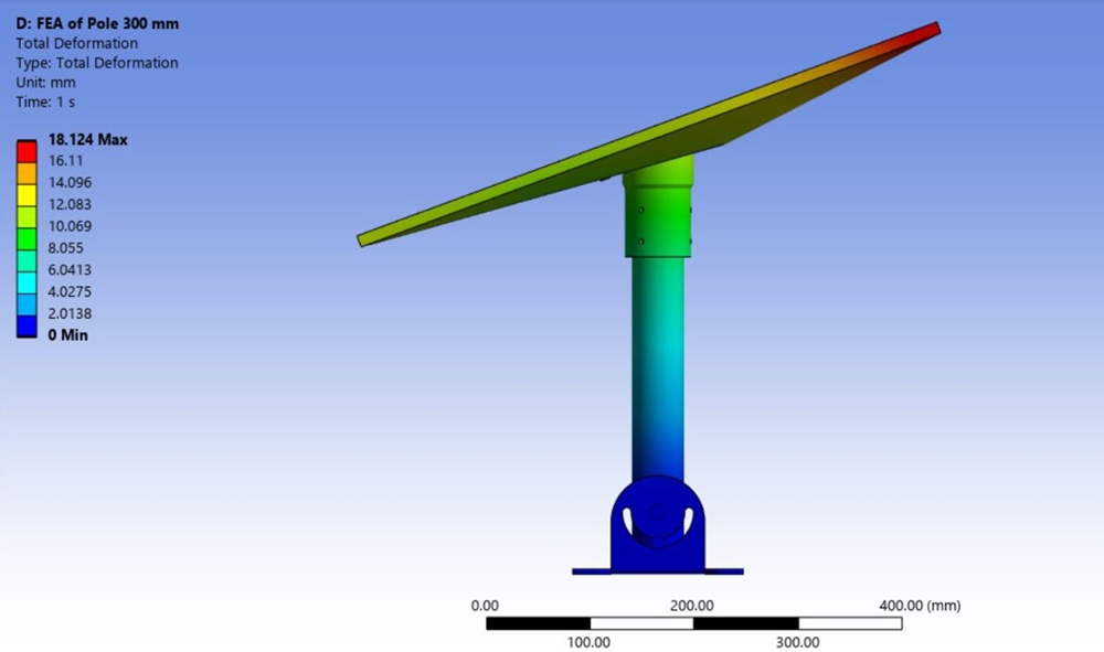
FEA total deformation, 300 mm pole at 248 km/h. Maximum deformation 18.1 mm, well within safe structural limits. Source: Air Vision Systems Compliance Pack 2025
3,000 mm pole, maximum length configuration, produced the worst outcome by a significant margin. Maximum equivalent stress at the base of the pole reached 14,589 MPa, a result driven almost entirely by the bending moment that builds as the lever arm lengthens. The stress concentration at the base bracket connection is the critical failure point in this configuration, and the FEA makes clear that a 3,000 mm pole at 248 km/h represents a genuinely high-risk installation.
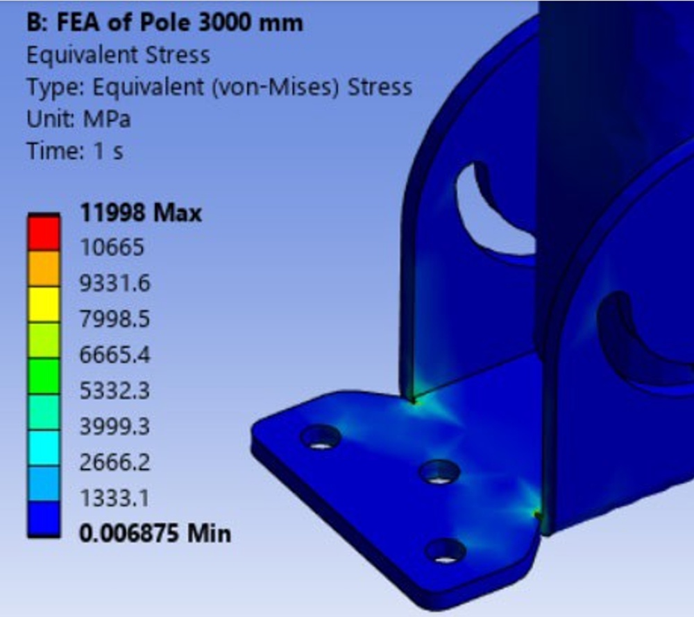
FEA equivalent stress, 3,000 mm pole at 248 km/h. Stress concentration at base bracket confirms the risk of long pole configurations in high wind. Source: Air Vision Systems Compliance Pack 2025
Bracket orientation load cases provided direct evidence of how the mounting configuration at the wall or roof interface affects load distribution. At the same 300 mm pole length and wind input, switching the bracket from its standard orientation to a vertical mounting position reduced total deformation from 18.1 mm to 15.5 mm, a measurable improvement from bracket position alone, with no change to pole length, wall thickness, or wind load. The results confirm that bracket orientation influences how bending moment transfers into the fixing points, and that an incorrectly positioned bracket compounds the structural demands created by a longer pole.
The overall conclusion from the FEA is unambiguous: every additional millimetre of pole length increases the structural load your mount has to manage, and the rate of increase is not forgiving. The gap between 300 mm and 3,000 mm is not a matter of degree. It is the difference between a structurally sound installation and one that is operating at the limits of what the hardware can handle.
What “Keep It Short” Actually Means in Practice
The engineering recommendation is consistent throughout the analysis: keep the pole as short as your installation allows. But what does that mean in practice, for real installs on real rooftops?
The starting point is sky clearance. Unlike traditional satellite dishes that must point at a fixed geostationary satellite, Starlink’s constellation now comprises over 10,000 active satellites in low Earth orbit, constantly moving across the sky. The Gen 3 dish uses a phased array antenna with a 110-degree field of view that electronically steers the signal to track satellites as they pass overhead. It does not need to point in any particular direction. What it does need is a clear, unobstructed 110-degree cone of sky.
The Starlink app’s obstruction tool is the practical way to determine the minimum pole height needed at your specific location. Stand at the proposed mount point, scan the sky, and let the app tell you whether you have a clear enough view. That result, not guesswork, not aesthetics, is what should determine your minimum pole length.
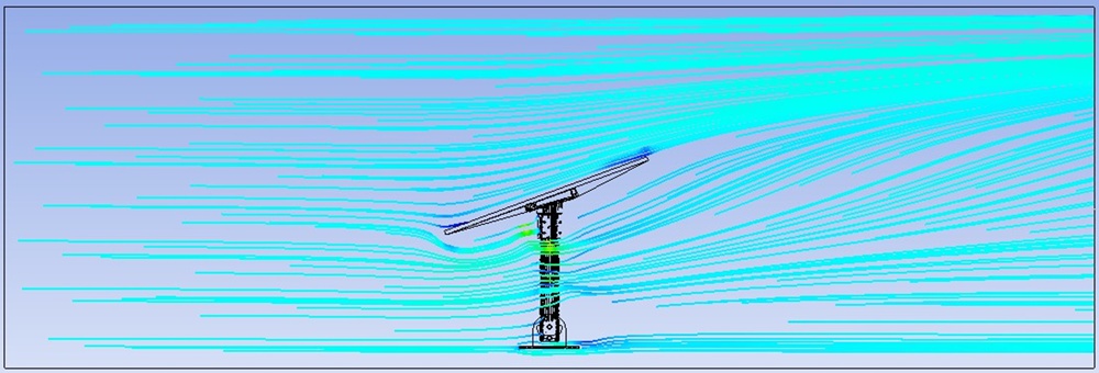
CFD streamline analysis of Wellington wind conditions at 248 km/h. A shorter pole keeps the dish in the lower, more sheltered part of the wind profile. Source: Air Vision Systems Compliance Pack 2025
Once you have the minimum clearance length, the parametric optimisation data from the engineering analysis gives a clear framework for what wall thickness you need to support it safely. The figures below are based on the worst-case wind input of 248 km/h. At 124 km/h, a more typical severe storm condition, wind pressure drops to one quarter of the peak value, meaning each wall thickness can safely support longer pole extensions than the 248 km/h limits.
3 mm wall thickness supports pole lengths up to 500 to 600 mm at 248 km/h. At 124 km/h the significantly reduced pressure means this specification can accommodate longer extensions, making it suitable for sheltered suburban installs where gusts are unlikely to approach worst-case conditions.
4 mm wall thickness supports pole lengths of 600 to 700 mm at 248 km/h. At 124 km/h this specification comfortably handles mid-range pole lengths, a typical residential roof mount in most New Zealand and Australian conditions.
5 mm wall thickness supports pole lengths of 700 mm and above at 248 km/h, and is the recommended specification for any exposed site regardless of wind speed. For Wellington rooftops, coastal sites, and elevated rural installs, 5 mm is the specification to use, because exposed sites can and do reach the upper end of the wind range.
The practical implication is straightforward: if your install requires a longer pole to clear an obstruction, the answer is not to use whatever pole is easiest to source. It is to step up the wall thickness to match the length. A 900 mm pole in 3 mm wall aluminium is not the same structural proposition as a 900 mm pole in 5 mm wall aluminium, and on an exposed site at 248 km/h, that difference is the margin between a compliant installation and a failure.
One more practical point: the engineering analysis shows that the sheltering effect of the roof surface matters. A pole that sits close to the roof keeps the dish in the lower, more sheltered part of the wind profile. Every extra 100 mm of height moves the dish further into the free airstream, where wind speeds are higher and aerodynamic load increases. Keeping the pole short is not just about bending moment. It is about reducing the wind input to the structure in the first place.
Once you have settled on the right pole length and wall thickness, the Air Vision Systems Starlink Gen 3 Clip-In Pole Adapter is the bracket engineered to attach it to your Gen 3 dish.
When You Can’t Go Short: Managing Longer Pole Installations
The engineering recommendation is clear: keep the pole as short as possible. But some installations genuinely require more length, a roofline that extends well above the proposed mounting point, a parapet that blocks the required sky view, or a chimney or tree that cannot be avoided without additional height. In these cases, the question is not whether to use a longer pole. It is how to manage the increased structural demands that come with it.
The engineering analysis provides a practical framework for doing exactly that. The parametric optimisation data shows that by stepping up wall thickness alongside pole length, installers can maintain a structurally compliant installation even at extended lengths. A 5 mm wall thickness pole supports lengths of 700 mm and above at 248 km/h, which covers the majority of installs that genuinely require extended height. Beyond that, the analysis recommends keeping every other variable as conservative as possible: correct bracket orientation, correctly specified fasteners, and the converter mounted as close to the power source as practicable to minimise input cable length.
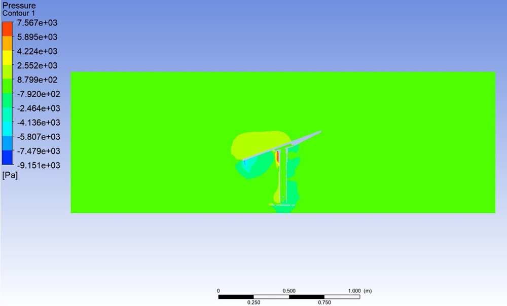
CFD pressure contour, 300 mm pole at 248 km/h. Maximum pressure 7,567 Pa. Source: Air Vision Systems Compliance Pack 2025
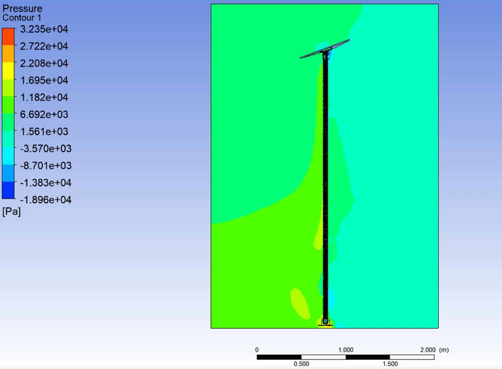
CFD pressure contour, 3,000 mm pole at 248 km/h. Maximum pressure 32,346 Pa, more than four times the short pole result. Source: Air Vision Systems Compliance Pack 2025
Bracket placement and orientation deserve particular attention on longer pole installations. The FEA results show that the bracket is the critical stress concentration point in the assembly. It is where bending moment transfers from the pole into the fixing surface. On a long pole under high wind load, an incorrectly positioned bracket or undersized fixing compounds the structural demands significantly. Use the correct bracket for the surface type, roof versus wall, and ensure fixing points are into solid structure, not just cladding or soffit material.
Finally, if your install genuinely requires a pole length at the upper end of the range, approaching or exceeding 1,000 mm, the engineering analysis strongly supports using the Starlink app’s obstruction tool to verify that a shorter pole really cannot achieve the required sky view before committing to a long configuration. In many cases, repositioning the mount by even half a metre can reduce the required pole length significantly, bringing the installation back into a more conservative structural zone. That is always the better outcome if the site allows it.
Did You Know?With over 10,000 active Starlink satellites now in low Earth orbit, the dish does not need to point in any particular direction. Its phased array antenna electronically steers the signal across a 110-degree field of view to track satellites as they pass overhead. The one thing that does matter is that the dish face is pointing skyward, not sideways or downward, since it cannot track satellites through a roof or a wall. Beyond that, the single most important factor in choosing your pole length is the minimum height needed to achieve a clear, unobstructed 110-degree cone of sky above whatever is blocking your view. Get that number right first, and the rest of your install decisions follow from it.
Air Vision Systems stocks a full range of Starlink mounting solutions designed and tested for New Zealand and Australian conditions, the right hardware for your install, whatever your site demands.
Browse the full range at Air Vision Systems
Frequently Asked Questions
How long should my Starlink pole be?
As short as your installation allows while still achieving a clear, unobstructed 110-degree cone of sky above any nearby obstructions. Use the Starlink app’s obstruction tool to determine the minimum height needed at your specific location, that number, not aesthetics or convenience, should drive your pole length decision. The engineering analysis shows that every extra millimetre of pole length increases the structural load on your mount, so the minimum compliant length is always the right answer.
Does pole length really affect how my Starlink mount performs in wind?
Yes, significantly. The engineering analysis recorded a maximum pressure of 7,567 Pa on a 300 mm pole and 32,346 Pa on a 3,000 mm pole under the same 248 km/h wind input. At 124 km/h, where wind pressure drops to one quarter of the peak value, the pressure figures reduce substantially, but the relationship between pole length and structural load remains the same. The bending moment at the base of the mount increases dramatically with pole length at any wind speed, which is why the structural recommendation is to keep the pole as short as possible and match wall thickness to length.
What wall thickness do I need for my Starlink pole?
The engineering analysis recommends 3 mm wall thickness for pole lengths up to 500 to 600 mm, 4 mm for 600 to 700 mm, and 5 mm for anything longer or any exposed site install. At 248 km/h these are the specifications that keep the mount within safe structural limits. At 124 km/h, where wind pressure drops to one quarter of the peak value, each thickness can support longer extensions, but 5 mm remains the recommendation for any exposed coastal, elevated, or Wellington site regardless of expected conditions.
Can I use a longer pole if I need more clearance?
Yes, but the wall thickness must be stepped up to match. A longer pole creates a greater bending moment under wind load, and a thicker wall is what compensates for that increased demand. The engineering analysis is clear that the combination of pole length and wall thickness, not just one or the other, determines whether the installation is structurally compliant.
Does it matter which direction my Starlink dish faces?
No, the Gen 3 dish uses a phased array antenna with a 110-degree field of view that electronically steers the signal to track satellites as they pass overhead. It does not need to point in any particular compass direction. What does matter is that the dish face is pointing skyward, and that it has a clear, unobstructed 110-degree cone of sky above it. Use the Starlink app’s obstruction tool to verify this before finalising your mount location and pole length.
What the Engineering Tells Us
Pole length is the decision most Starlink installers give the least thought to, and the one that has the biggest structural consequence when conditions test the installation.
The engineering analysis behind this post makes that relationship quantifiable: a 3,000 mm pole generates more than four times the wind pressure of a 300 mm pole under the same 248 km/h input, and the bending moment at the base grows with every extra millimetre of height.
Even at 124 km/h, where wind pressure drops to one quarter of the peak value, the relationship between pole length and structural load remains the same. The minimum compliant pole length for your site, matched to the correct wall thickness, is always the right specification at any wind speed.
The practical framework from the analysis is straightforward. Start with the Starlink app’s obstruction tool. Find the minimum pole height that gives your Gen 3 dish a clear, unobstructed 110-degree cone of sky.
Match your wall thickness to that length, 3 mm up to 500 to 600 mm, 4 mm up to 600 to 700 mm, and 5 mm for anything longer or any exposed site. At 248 km/h these are the specifications that keep the mount within safe structural limits. At 124 km/h each thickness can support longer extensions, but 5 mm remains the recommendation for any exposed coastal, elevated, or Wellington site regardless of expected conditions.
Specify the fasteners correctly, position the bracket properly, and mount the converter close to the power source to keep the high-current input section as short as possible. Those decisions, made correctly from the start, are what separate a compliant installation from one that is guessing at the margin.
For New Zealand and Australian installers working on exposed rooftops, coastal sites, or anywhere in Wellington, these are not theoretical considerations. The wind conditions this analysis tested against are real, they occur, and the difference between a correctly specified mount and an incorrectly specified one is not always visible until it matters most.
The findings in this post come from CFD and FEA engineering analysis commissioned by Air Vision Systems, covering Starlink Gen 3 mount hardware tested against wind conditions up to 248 km/h. The same engineering methodology behind the full Air Vision Systems Starlink compliance series, so the numbers are consistent and traceable.
Once you’ve settled on the right pole length for your site, our Buyer’s Checklist walks through the remaining checks: wall thickness, outer diameter, and consistency along the pole, before you buy.
Browse the full Air Vision Systems mount range at Air Vision Systems or use our free Air Vision Systems Smart Cable Calculator to check your cable run at the same time.