Ordering the wrong cable length is one of the most common and most avoidable mistakes in a Starlink install. Too short and you are pulling the cable tight, stressing the connectors, or worse – having to reorder and wait. Too long and you have excess cable to manage, coil, and hide.
Getting the length right before you buy takes about ten minutes with a tape measure and a bit of planning. This guide walks you through exactly how to do it – for both the Starlink Gen 3 and the Starlink Mini – so you arrive at a confident number before you place your order.
Once you have your measurement, the Air Vision Systems AVS Starlink Smart Cable Calculator will match you to the right cable and power components for your terminal and power source in seconds.
Why Most People Get the Length Wrong
The most common mistake is measuring in a straight line from the dish to the router or power source. That number is almost always shorter than the cable you actually need.
Real installs never run in straight lines. The cable has to travel down a wall, along a ceiling, around a door frame, through a roof penetration, down into a cabinet, or along the underside of a vehicle chassis. Every change of direction adds length, every drop from a roof or wall adds length, and every loop around an obstacle adds length.
The second most common mistake is measuring to where the router or power source is right now, without accounting for where it needs to be once the install is finished. A router that sits on a desk during planning often ends up mounted on a wall or tucked into a cabinet once the install is done – and that changes the required cable length.
The third mistake is ordering the exact measured length with no margin. Cables need a small service loop – a gentle coil of slack – at both ends to allow for connector strain relief, future adjustments, and the reality that measurements in the field are rarely perfectly accurate.
The rule is simple: measure the route, not the distance. Then add a margin. The sections below show you how.
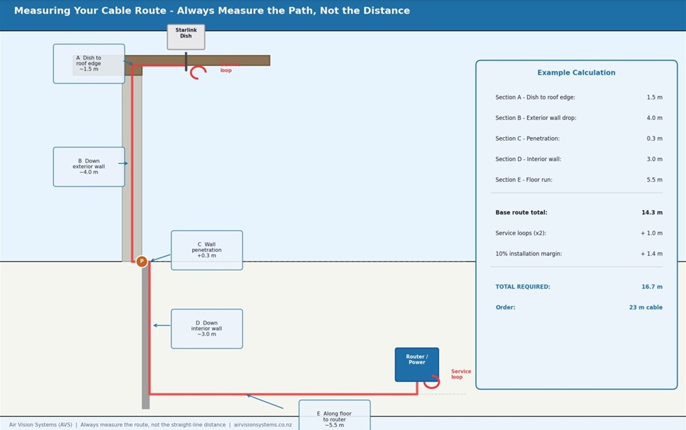
Measuring a cable route correctly – each section measured along the actual path, with service loops at both ends and a 10% installation margin added. Air Vision Systems.
Step One: Map Your Cable Route Before You Measure
Before you pick up a tape measure, walk the route the cable will actually travel and note every section.
For a typical residential Gen 3 install the route might look like this: from the dish on the roof, down the exterior wall to a penetration point, through the wall, along an interior wall to the router location.
Each of those sections is a separate measurement, and they all add up.
For a vehicle or caravan Mini install the route might look like this: from the dish mount on the roof, through a roof entry gland, down the interior wall or under the lining, along the floor or under a bench seat, to the power source location. Again, each section is separate.
Walk the full route and write down every section before you measure anything. It helps to sketch a rough diagram – it does not need to be accurate, just enough to remind you of every segment when you are measuring.
Things to note as you walk the route:
• Every vertical drop or rise
• Every corner or direction change
• Any sections where the cable runs inside conduit, under lining, or through tight spaces that may require extra slack
• The location of any grommets, entry points, or penetrations the cable needs to pass through
• Where the cable will terminate at the power source or router end
Once you have mapped the full route you are ready to measure it accurately.
Step Two: Measure Each Section of the Route
With your route mapped, measure each section individually and write down each figure. Do not try to estimate – measure each one with a tape measure or a length of string that you can then measure against a tape.
A few practical tips for accurate measurement:
For roof to wall drops, measure from the dish mounting point down to where the cable exits the roofline – not from the peak of the roof. The cable travels with the structure, not through the air.
For wall runs, measure along the wall surface, not diagonally. If the cable clips along a skirting board or follows a cable tray, measure that path.
For through-wall penetrations, add 300 mm for each penetration point to account for the cable passing through insulation, wall thickness, and the fitting on each side.
For vehicle and caravan installs, run a length of string or pull wire along the intended route before measuring. This gives you the true routed length including any curves around structural members, over wheel arches, or under floor sections.
For tight or hidden runs, add 10 to 15 percent to that section’s measurement to allow for the cable to follow the contours of the space rather than taking a perfectly straight path.
Once you have a measurement for every section, add them all together. That total is your base route length.
Step Three: Add Your Service Margin
Your base route length is not the number you order. Every installation needs a service margin added on top – a small amount of extra cable at each end that allows for strain relief, future adjustments, and the inevitable small differences between a planned route and a finished install.
The standard service margin for a Starlink cable installation is:
• Add 500 mm at the dish end for a service loop at the mounting point. This allows the cable to connect to the dish without pulling tight, protects the connector from strain, and gives you enough slack to disconnect and reconnect the terminal without unmounting it.
• Add 500 mm at the power source or router end for the same reason. Equipment gets moved, repositioned, and replaced. A small service loop at the termination end means you can work with the cable without having to pull it through the wall or lining again.
• Add 10 percent to the total route length as a general installation margin. Measurements in the field are rarely perfectly accurate, routes change slightly during installation, and cable does not always travel exactly the path you planned.
The calculation looks like this: base route length, plus 1 metre for service loops at both ends, plus 10 percent of the base route length as installation margin. Round up to the nearest available cable length rather than rounding down.
If you are between two available lengths, always choose the longer one. A cable that is slightly too long is manageable. A cable that is slightly too short means starting over.
Worked Examples: Gen 3 Residential and Mini Caravan Install
The best way to understand the measurement process is to see it applied to two real scenarios.
Example 1 – Gen 3: Residential Roof Install
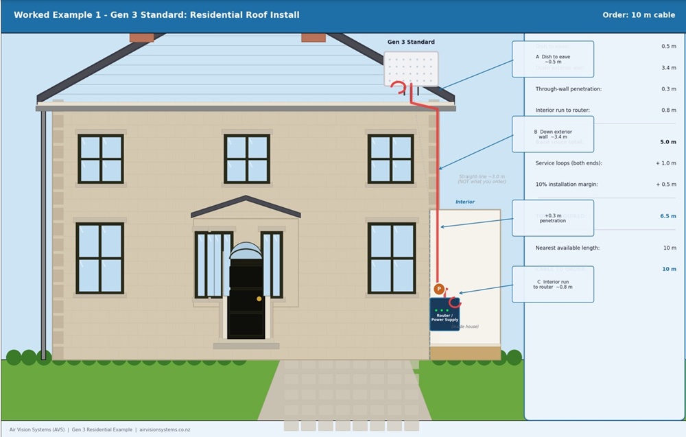
Gen 3 residential roof install – cable route measured section by section with penetration allowance, service loops, and 10% margin added. Total required 6.5 m – order 10 m. Air Vision Systems.
Example 2 – Starlink Mini: Caravan Install
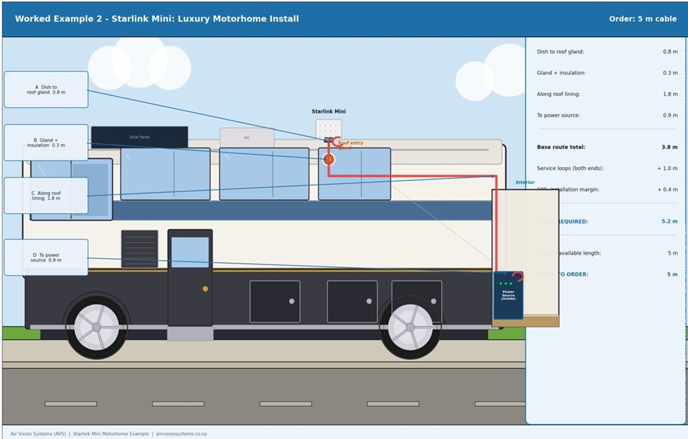
Starlink Mini caravan roof install – cable routed through roof entry gland, down wall lining, under bench seat to power source. Total required 5.2 m – order 5 m. Air Vision Systems.
In both examples the straight-line distance would have significantly underestimated the required length. The residential install measured roughly 3.0 m in a straight line but required a 10 m cable. The caravan install measured roughly 2.2 m in a straight line but required a 5 m cable. The difference is the route, the penetrations, and the margin.
The Quick Measurement Checklist
✓ Walked the full cable route and noted every section
✓ Measured each section individually along the actual route – not in a straight line
✓ Added 300 mm for each through-wall or through-roof penetration
✓ Added 500 mm service loop allowance at the dish end
✓ Added 500 mm service loop allowance at the power source or router end
✓ Added 10 percent to the total as an installation margin
✓ Rounded up to the nearest available cable length
Got your measurement? The calculator takes it from there.
Enter your Starlink system, power source, and required cable length into the Air Vision Systems AVS Starlink Smart Cable Calculator. It matches your setup to the right cable and power components in seconds.
Use the Air Vision Systems AVS Starlink Smart Cable Calculator
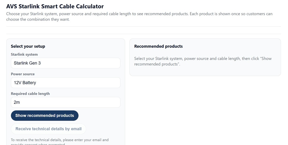
The Air Vision Systems AVS Starlink Smart Cable Calculator – enter your terminal, power source and cable length to get the right product recommendation.
Frequently Asked Questions
What if my required length falls between two available cable lengths?
Always order the longer option. A cable that is slightly longer than your measured requirement is easy to manage – the service loop at each end absorbs the extra length neatly, and a small amount of additional coil at the power source end is not a problem in most installations. A cable that is even slightly too short cannot be stretched, and the consequences range from stressed connectors and poor contact to having to reorder entirely. The 10 percent installation margin in the measurement process is designed to push your calculated length above the shorter option in most cases, but when in doubt always round up.
Can I join two shorter cables together to make a longer run?
For 30 V DC two-conductor cable, joining two cables is technically possible provided the total combined length stays within the compliance limit for your conductor gauge and any coupler used is correctly rated for the voltage and current involved. However, every junction point introduces contact resistance and a potential failure point, particularly in outdoor, vehicle, and marine environments where vibration, moisture, and temperature cycling put stress on connections. A single continuous cable is always the preferred solution. The Air Vision Systems DC to DC cable for Starlink Mini is available in lengths from 2 m to 15 m, which covers the majority of installation scenarios.
Does the cable length affect the power delivery to my Starlink terminal?
Yes – this is exactly what the Air Vision Systems engineering reports address. Every cable has resistance, and the longer the cable the more voltage is lost between the power source and the terminal. Beyond the maximum compliant lengths for each conductor gauge and voltage, the terminal will receive less than 90 percent of the source voltage and performance will be affected. This is why the measurement process matters – not just for physical fit but for electrical compliance. If your measured route length approaches the limits for your chosen conductor gauge and voltage, use the Air Vision Systems AVS Starlink Smart Cable Calculator to confirm compliance before ordering.
I have already bought a cable that is too short – what are my options?
The correct solution is to replace it with the right length. For Starlink Mini, the Air Vision Systems DC to DC cable is available in 2 m, 3 m, 5 m, 10 m, and 15 m lengths. For the Gen 3, the Air Vision Systems waterproof replacement cable is available in lengths from 5 m up to 46 m. Check the cables page at airvisionsystems.co.nz/cables for the full range for your terminal. For USB-C PD cables the total cable length must not exceed 5 m with a certified e-marked 5 A cable – if your current cable is too short for your route, consider switching to 30 V DC distribution instead, which supports longer runs. Attempting to stretch a short cable or force a connection under tension will stress the connectors and is likely to cause intermittent faults or connector failure over time.
Does it matter which end of the cable connects to the dish versus the power source?
For the Air Vision Systems DC to DC power cable, both ends use the same Male DC connector, so either end can connect to either device – there is no incorrect orientation for this cable type. For cables with different connectors at each end – such as USB-C to DC cables or multi-function cables with a car adapter on one end – the correct orientation is obvious from the connector type itself. If you are ever unsure, the product page for your specific cable on the Air Vision Systems website confirms the connector type at each end in the product specifications.
Measure Once, Order Right, Install Clean
The most expensive cable mistake is not ordering the wrong brand or the wrong gauge – it is ordering the wrong length. Too short means starting over. Too long is manageable. The ten minutes you spend measuring the route properly before you order saves hours of frustration on installation day.
The process is the same regardless of whether you have a Starlink Gen 3 or a Starlink Mini. Map the route, measure each section along the actual path the cable will travel, add for penetrations and direction changes, add your service loops at both ends, add ten percent as an installation margin, and round up to the nearest available length.
Once you have that number, the Air Vision Systems AVS Starlink Smart Cable Calculator matches it to the right cable and power components for your specific terminal and power source. It takes the guesswork out of the product decision once you have done the measurement work.
Air Vision Systems manufactures cables specifically for Starlink installs in a range of lengths for both the Gen 3 and the Starlink Mini. If you know your run length, the right cable is in the range.
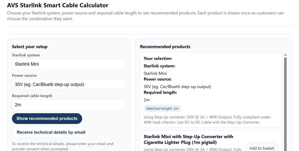
Air Vision Systems AVS Starlink Smart Cable Calculator showing recommended products for a Starlink Mini installation – matched to your terminal, power source and run length.
Use the Air Vision Systems AVS Starlink Smart Cable Calculator