It’s one of the most common questions from Starlink Mini owners planning an install: how far can I actually run the cable?
The honest answer is that it depends – on your voltage, your cable gauge, and your power source. Ask on a forum and you’ll get a dozen different opinions. Some will say 10 metres, some will say 50, and most won’t explain why.
This post gives you the verified answer, calculated from electrical engineering compliance reports prepared for Air Vision Systems. Every figure in this post is traceable to copper conductor resistance data, verified voltage drop calculations, and a 90% minimum voltage retention criterion aligned with IEEE 802.3bt, IEC 60228, and AS/NZS 3000.
There is no guesswork here. There is a number for every scenario, and the Air Vision Systems AVS Starlink Smart Cable Calculator will find yours in seconds once you know your setup.
The Engineered Answer – Starlink Mini Maximum Cable Runs
At 20 V USB-C PD:
• Compliant up to 5 m with a certified e-marked 5 A cable
At 30 V regulated DC (two-conductor cable):
• 20 AWG: compliant up to 30 m
• 18 AWG: compliant up to 60 m
• 16 AWG: compliant up to 90 m
At 48 V structured backbone (Cat6A 24 AWG):
• Compliant up to 90 m with local step-down converter near terminal
At 57 V structured backbone (Cat6A 24 AWG):
• Compliant up to 100 m with local step-down converter near terminal
Direct 12 V supply:
• Non-compliant beyond 2 to 3 m – step-up converter to 30 V required for all meaningful runs
All figures calculated using verified copper conductor resistance values at 25 degrees Celsius with a 90% minimum voltage retention criterion at the terminal input. Source: Air Vision Systems Engineering Compliance Reports.
Why the Answer Depends on Your Voltage
Before we get to the numbers, it helps to understand why there isn’t one single answer for every Starlink Mini install.
Every cable has resistance. The longer the cable, the more resistance, and the more voltage is lost between your power source and the terminal. This is called voltage drop. The Air Vision Systems engineering reports use a strict pass/fail criterion: the terminal must receive at least 90% of the source voltage at all times. Drop below that and you risk dropouts, instability, or the terminal failing under load.
The key variable is voltage. Higher voltage means lower current for the same power load. Lower current means less voltage drop per metre of cable. Less voltage drop means you can run the cable further before hitting the 90% limit.
The Starlink Mini supports two power inputs:
• 20 V USB-C Power Delivery for short runs
• 30 V regulated DC for longer installations
It can also be served by a 48 V or 57 V structured cabling backbone with a local step-down converter near the terminal. Each of these configurations has a different maximum cable length – and that is exactly what the engineering reports calculate.
The figures that follow are not estimates. They are calculated results, verified against copper conductor resistance data at 25 degrees Celsius.
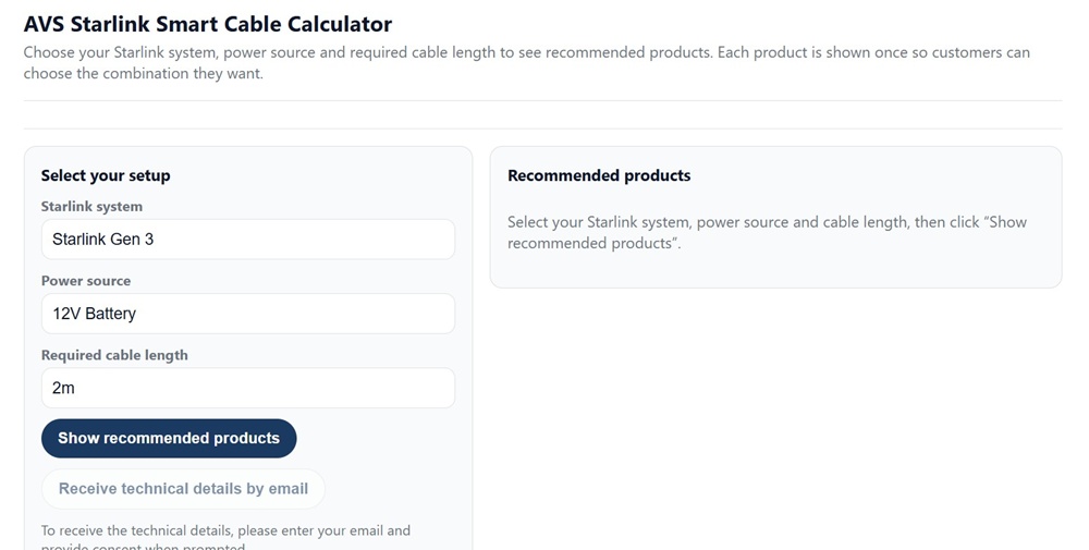
Figure 1 – The Air Vision Systems AVS Starlink Smart Cable Calculator – select your Starlink system, power source and required cable length to get the right product recommendation.
USB-C Power Delivery at 20 V: Maximum 5 m
The simplest way to power a Starlink Mini is via USB-C Power Delivery at 20 V. This is the option most people start with – a power bank, a mains PD adapter, or the USB-C PD port on a portable power station like the Bluetti AC2P.
The Air Vision Systems engineering report confirms that USB-C PD at 20 V is compliant up to 5 m with a certified e-marked 5 A cable. The voltage drop at 5 m remains within the 90% compliance threshold, and the Air Vision Systems cable calculator confirms 5 m as the working limit for this configuration.
There are two non-negotiable requirements for this to work:
• The cable must be e-marked and certified for 5 A continuous current. A non-e-marked cable is limited to 3 A and is not suitable for powering the Mini at full load over this distance.
• Beyond 5 m, USB-C PD is not the right solution. Switch to 30 V regulated DC distribution for any run longer than 5 m.
The USB-C PD path is ideal for desk setups, portable use, and short vehicle installs where the power source is close to the terminal. For anything longer, the 30 V DC path is the correct choice.
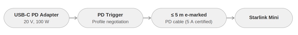
Figure 2 – Direct USB-C PD adapter and ≤ 5m certified cable powering Starlink Mini
System architecture: Direct USB-C PD adapter with certified e-marked cable powering Starlink Mini. Maximum cable length is 5 m with a certified e-marked 5 A cable. Source: Air Vision Systems Engineering Compliance Reports
30 V Regulated DC: The Right Choice for Longer Runs
For any Starlink Mini installation where the cable needs to run further than 5 m, 30 V regulated DC is the correct power path. This is the native DC input voltage of the Mini, and it is what the Air Vision Systems engineering reports use as the primary reference for cable length calculations.
At 40 W and 30 V, the current in the cable is 1.33 A. That is low enough to allow meaningful cable runs on standard two-conductor DC cable, with the maximum distance determined by the conductor gauge.
The Air Vision Systems engineering report confirms the following safe cable lengths at 30 V under a continuous 40 W load:
20 AWG two-conductor cable
• Maximum compliant run: 30 m
• Voltage drop at 30 m: 0.82 V
• Load voltage at 30 m: 29.18 V
• Result: Pass – 97.3% of source voltage retained
18 AWG two-conductor cable
• Maximum compliant run: 60 m
• Voltage drop at 60 m: 0.98 V
• Load voltage at 60 m: 29.02 V
• Result: Pass – 96.7% of source voltage retained
16 AWG two-conductor cable
• Maximum compliant run: 90 m
• Voltage drop at 90 m: 1.21 V
• Load voltage at 90 m: 28.79 V
• Result: Pass – 95.97% of source voltage retained
All three gauges pass comfortably within the 90% compliance threshold. The limiting factor in each case is not the pass criterion itself but the practical installation guideline that conductor gauge should be stepped up as run length increases to keep losses conservative and installation robust.

Figure 3 – 12 V supply stepped up to 30 V and delivered over 20 AWG cable to Starlink Mini
System architecture: 12 V supply stepped up to 30 V and delivered over 20 AWG two-conductor cable to Starlink Mini. Source: Air Vision Systems Engineering Compliance Reports
What About 12 V? Why Direct 12 V Supply Does Not Work
A lot of Starlink Mini installs start from a 12 V source – a vehicle battery, a caravan house battery, a portable power station DC output, or a solar system. It is the most common DC voltage in mobile and off-grid environments, so it is a natural starting point.
The problem is that the Starlink Mini does not accept 12 V as a direct input. It requires either 20 V USB-C PD or 30 V regulated DC. Connecting the terminal directly to a 12 V source without a converter is outside the device specification and will not work reliably.
Even if you use 12 V as a distribution voltage and accept the voltage drop implications, the Air Vision Systems engineering report is clear: at 40 W load, a 12 V source pushes 3.33 A through the cable. That current level causes significant voltage drop over very short distances. A 12 V supply is non-compliant as a direct feed beyond 2 to 3 m.
The correct solution is a step-up converter. Mount a 12 V to 30 V regulated DC-DC converter as close as possible to the 12 V source – vehicle battery, power station DC port, or solar controller output. The converter output then feeds the two-conductor DC cable run to the terminal at 30 V, and all the cable length limits in the previous section apply from that point.
The Air Vision Systems engineering report recommends a 12 V to 30 V converter rated at 3 A output (90 W) for Starlink Mini installations. This provides comfortable margin above the 40 W device requirement and is the reference converter used in all AVS compliance calculations.
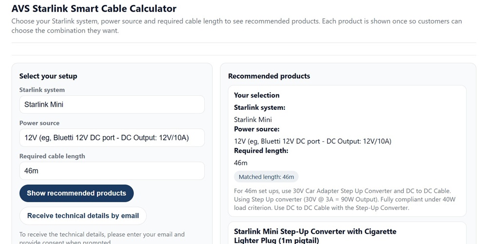
Figure 4 – Air Vision Systems AVS Starlink Smart Cable Calculator: Starlink Mini with 12V source at 46m – the calculator correctly identifies the step-up converter requirement and recommends the right products for a compliant installation.
Extended Runs: 48 V and 57 V Structured Cabling Backbones
For installations where even 90 m on 16 AWG is not enough, or where structured Ethernet cabling is already in place, both 48 V and 57 V distribution backbones can serve the Starlink Mini over longer distances with a local step-down converter placed near the terminal.
The principle is straightforward. Instead of running 30 V DC the full distance, you distribute at a higher voltage over Cat5e or Cat6A structured cabling, then step the voltage down to 30 V at the terminal end. Higher voltage means lower current, lower current means less voltage drop, and less voltage drop means a longer compliant run.
The Air Vision Systems engineering report confirms the following for structured cabling backbones using Cat6A 24 AWG with two pairs per polarity:
48 V backbone
• Maximum compliant run: 90 m
• Pass criterion: load voltage must be at or above 43.2 V at the step-down converter input
57 V backbone
• Maximum compliant run: 100 m
• Pass criterion: load voltage must be at or above 51.3 V at the step-down converter input
Cat5e and Cat6A are electrically equivalent for DC voltage drop at the same conductor gauge. Cat6A is the recommended choice for outdoor, marine, or demanding environments where mechanical durability and termination quality matter.
This architecture suits permanent installations in caravans, commercial vehicles, marine vessels, and buildings where a structured cabling run is already in place or where the installation warrants the additional infrastructure.
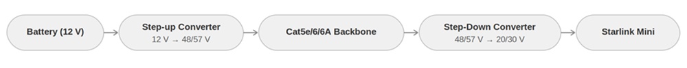
Figure 5 – 12 V stepped up to 48/57 V backbone, with local step-down converter near Starlink Mini
System architecture: 12 V supply stepped up to 48/57 V backbone over Cat5e/6/6A, with local step-down converter near Starlink Mini. Source: Air Vision Systems Engineering Compliance Reports
Engineering Note
The cable length limits in this post are drawn directly from Air Vision Systems electrical engineering compliance reports prepared to international standards including IEEE 802.3bt, IEC 60228, and AS/NZS 3000. All figures are calculated using verified copper conductor resistance values at 25 degrees Celsius and a 90% minimum voltage retention criterion at the terminal input. These are not estimates or general guidelines – they are engineered limits you can use with confidence in your installation planning.
Engineer’s Statement
“The analyses contained in this report were performed using standardised electrical engineering methods, verified copper conductor resistance data at 25 degrees Celsius, and a conservative 90 percent minimum voltage retention criterion aligned with IEEE 802.3bt, IEC 60228, and AS/NZS 3000.
All cable length limits, conductor sizing recommendations, and converter placement guidance presented here are traceable to the Air Vision Systems compliance reports and are suitable for use in installation planning and technical documentation.
Installers should verify end-to-end voltage under full load conditions prior to commissioning any installation.”
Electrical Engineer (PEC Registered) | Air Vision Systems Compliance Pack 2025
Know your run length? The calculator finds your cable.
Enter your Starlink system, power source, and required cable length into the Air Vision Systems AVS Starlink Smart cable calculator. It matches your setup to the right cable and power components in seconds – no calculations required.
Use the Air Vision Systems AVS Starlink Smart Cable Calculator
Frequently Asked Questions
Can I extend my existing Starlink Mini cable to make it longer?
It depends on the cable type and the total combined length. For USB-C PD cables, the total length including any extension must not exceed 5 m, and every cable in the chain must be certified e-marked 5 A. Adding a non-e-marked extension to a compliant cable makes the entire run non-compliant. For 30 V DC two-conductor cable, extensions are acceptable provided the total combined run stays within the limits for your conductor gauge – 30 m for 20 AWG, 60 m for 18 AWG, and 90 m for 16 AWG – and the connectors are rated for the current and voltage involved. Any connector junction adds contact resistance, so it is always preferable to run a single continuous cable where possible.
Does the cable length limit change if I am only using the Mini at low power?
Yes, technically. The Air Vision Systems engineering reports calculate limits at the worst-case continuous load of 40 W. At lower loads the current is lower, voltage drop is smaller, and the compliant run length increases. However, the figures in this post and in the cable calculator are based on 40 W because that is the maximum the terminal can draw, and an installation that only passes at low load will fail the moment the terminal hits peak demand. Always size your cable for the maximum load, not the average.
What happens if I use a thinner cable than recommended for my run length?
The terminal will receive less than 90% of the source voltage under full load. In practice this means intermittent dropouts, connection instability, or the terminal struggling to maintain a link during peak usage. In some cases the terminal may appear to work at low load but fail when demand increases. Persistent undervoltage can also stress internal components over time. Using undersized cable is one of the most common causes of Starlink Mini performance issues in vehicle and off-grid installations, and it is entirely preventable by matching your cable gauge to your run length using the Air Vision Systems AVS Starlink Smart Cable calculator before you buy.
Can I use a standard extension lead or DC cable from a hardware store?
In short, no – not without modification. While the electrical principle is straightforward, a standard DC cable from a hardware store will not have the correct connectors for the Starlink Mini. The Mini uses a specific DC barrel connector, and generic cables are not terminated to fit. Getting the connectors wrong means the cable simply will not connect, and attempting to modify connectors without the correct tooling and ratings introduces risk at the termination point. For USB-C PD cables, generic or unbranded cables carry an additional problem – e-marked certification is non-negotiable for the 5 m limit to apply, and most hardware store USB-C cables are not e-marked. The straightforward solution is to use cables manufactured specifically for Starlink Mini installs, with the correct connectors, verified AWG rating, and appropriate insulation for your environment. The Air Vision Systems cables page at airvisionsystems.co.nz/cables covers the full range with specifications for each product.
Do I need a different cable for indoor versus outdoor runs?
The electrical specifications are the same indoors and out – the AWG gauge limits in this post apply regardless of where the cable runs. What changes outdoors is the physical specification. Cables routed outside need UV-resistant insulation, appropriate strain relief at entry points, and corrosion-resistant connectors, particularly in marine or coastal environments. For vehicle installs, cables need to handle vibration and temperature cycling. Several Air Vision Systems cables in the range feature UV-resistant and wear-resistant construction – check the individual product specifications at airvisionsystems.co.nz/cables to confirm the right cable for your environment.
The Right Cable Starts With the Right Numbers
The question “how far can I run a Starlink Mini cable?” has a precise answer for every scenario – and now you have those answers, verified against engineering compliance reports rather than forum guesswork.
USB-C PD works up to 5 m with a certified e-marked 5 A cable. 30-volt regulated DC works up to 30 m on 20 AWG, 60 m on 18 AWG, and 90 m on 16 AWG. A high voltage backbone extends that further still. And if your only source is 12 V, a step-up converter mounted close to the source is the correct solution before any cable run begins.
Every one of those figures is a calculated engineering result, not an estimate. They come from the Air Vision Systems compliance reports prepared to IEEE 802.3bt, IEC 60228, and AS/NZS 3000 standards, and they are the same figures the Air Vision Systems AVS Starlink Smart Cable Calculator uses when it matches your setup to the right product.
If you know your power source and your run length, the calculator will do the rest. If you are still working out your setup, the figures in this post give you everything you need to plan it correctly before you buy.
Air Vision Systems manufactures cables specifically for Starlink installs – sized, terminated, and tested for the job. Browse the full range at airvisionsystems.co.nz/cables.
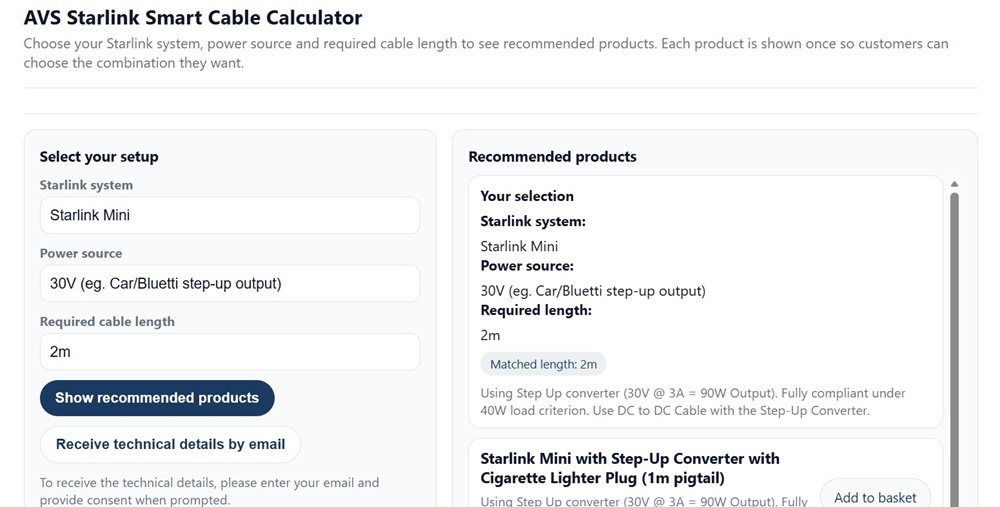
Figure 6 – Air Vision Systems AVS Starlink Smart Cable Calculator: Starlink Mini with 30V step-up output – showing full product recommendations including matched cable lengths and step-up converter options.
Ready to find the right cable for your install?
Use the Air Vision Systems AVS Starlink Smart Cable Calculator to find the right cable for your terminal, power source, and run length.
Use the Air Vision Systems AVS Starlink Smart Cable Calculator