Based on engineering analysis commissioned by Air Vision Systems | NZ, AU and Global
If you’re mounting a Starlink Gen 3 dish on a pole, one question matters more than anything else: will it stay put when the weather turns ugly? The clip-in design is clean and fast to install, but for rural properties, coastal sites, and anywhere that sees serious wind, you need more than a tidy fit. You need proof.
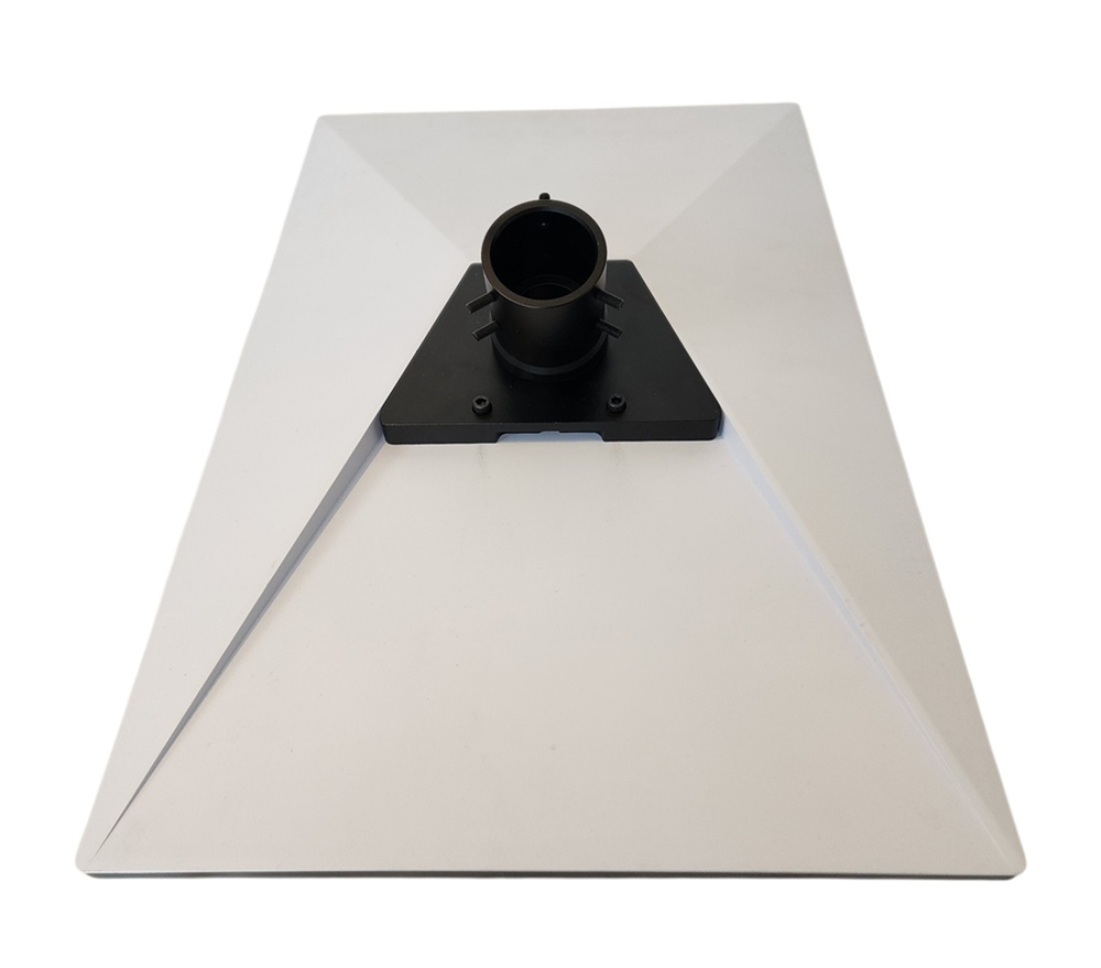
AVS Starlink Gen 3 Clip-In Pole Adapter – Heavy Duty Cast Aluminium
At Air Vision Systems, we don’t leave that to guesswork. Our Gen 3 Clip-In Pole Adapter is cast from ADC12/A383 aluminium alloy and has an independently verified Starlink Gen 3 pole adapter wind rating, backed by a full computational engineering assessment, Computational Fluid Dynamics (CFD) to calculate real wind pressure loads, and Finite Element Analysis (FEA) to test how the bracket responds to those loads. Used by installers across New Zealand, Australia, Europe and the UK, it is built to perform in the real world. The wind speed used as the basis for testing? 248 km/h, the maximum wind speed ever recorded in Wellington, one of the windiest cities on the planet. Here’s what the numbers show.
What Is CFD Wind Load Testing?
Before we get into the numbers, it helps to understand what CFD actually is and why it produces more reliable results than a back-of-envelope calculation.
Computational Fluid Dynamics is a simulation method that models how air moves around a physical object. In this case, airflow was directed perpendicularly onto the surface of the Starlink dish at 248 km/h. The simulation identifies the stagnation point, the spot on the dish where airflow velocity drops to zero and pressure peaks. That peak pressure figure is then used as the load input for structural testing.
For this assessment, the maximum pressure recorded at the stagnation point was 7,030 Pa. Rather than applying that only to the peak zone, the analysis applied it uniformly across the entire dish surface, a deliberately conservative approach that ensures the structural test reflects a worst-case scenario, not an average one.
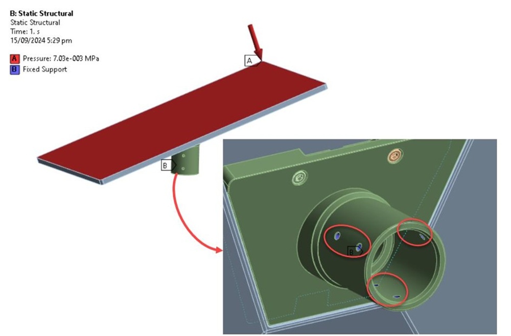
CFD simulation showing maximum pressure load at 248 km/h – stagnation point highlighted
The 248 km/h Test Case
The 248 km/h wind speed used in this assessment is not an arbitrary number. It’s drawn from official climate records for Wellington, New Zealand, a city widely regarded as one of the windiest in the world. Using the maximum recorded wind speed as the test basis means the bracket is assessed against the most extreme real-world condition on record, not an average or a theoretical estimate.
To put that in context, 248 km/h sits firmly in the territory of severe tropical cyclone conditions. For the vast majority of installations across New Zealand, Australia, Europe and the UK, the actual wind loads experienced will be significantly lower. That gap between test conditions and typical real-world loads is exactly where your margin of safety lives, and it is a meaningful one.
How the Bracket Was Analysed (FEA)
Once the CFD pressure load was established, it was transferred into a Finite Element Analysis (FEA) simulation using ANSYS Mechanical to assess how the bracket actually responds under that load. FEA works by breaking the component down into a mesh of small elements, in this case 980,100 tetrahedral elements, and calculating how stress distributes across the structure when force is applied.
The mesh was refined specifically around the bolt zones, where stress concentrations are highest, to ensure the results in those critical areas were as accurate as possible. The bracket was then fixed at all mounting positions to simulate real installation conditions, and the 7,030 Pa pressure load was applied to the dish face.
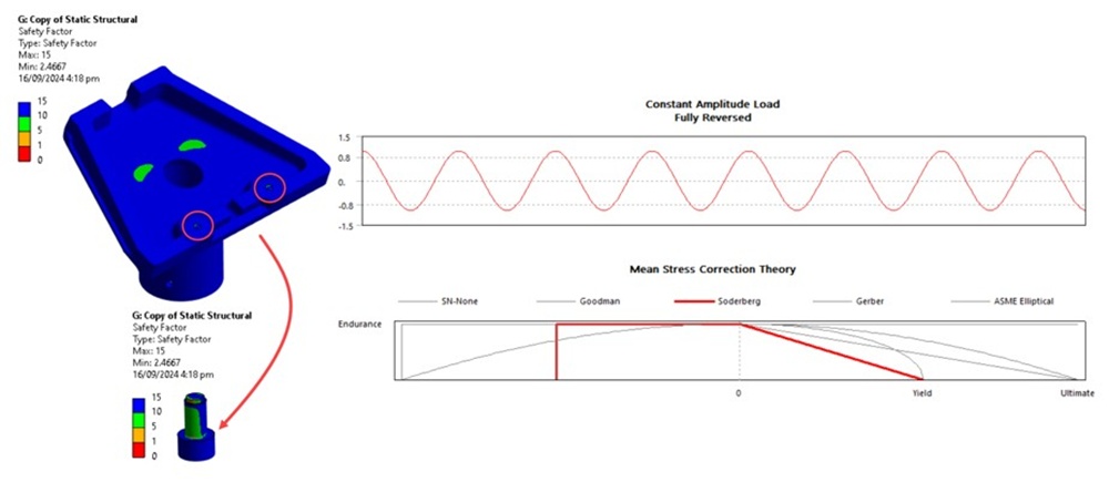
The analysis did not just look at a single static load event. It assessed fatigue performance under fully reversed cyclic loading, meaning the bracket was virtually subjected to 1,000,000,000 load cycles. The Soderberg method was used to calculate fatigue life, which is the most conservative of the available mean-stress correction approaches. It accounts for both the mean stress and the alternating stress in every cycle, giving a more demanding assessment than methods like Goodman or Gerber.
Why Pole Length Matters
The 7,030 Pa pressure figure used in the main structural assessment represents one specific configuration. But the Gen 3 Clip-In Pole Adapter is used across a wide range of installations, from a short post close to a roofline to a pole extending well above it. So a separate CFD comparison was run to understand how pole length itself affects the load the bracket has to resist.
The comparison tested two pole length extremes, 300 mm and 3,000 mm, under the same 248 km/h wind input. The difference in results is the clearest illustration in the entire analysis of why pole length matters so much.
At 300 mm pole length, the dish sits close to the mounting surface, operating in the lower, more sheltered part of the wind profile. The CFD recorded a maximum pressure of 7,567 Pa under these conditions.
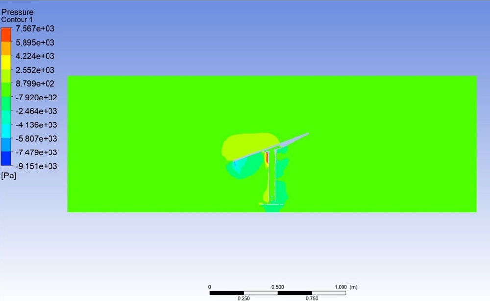
CFD pressure contour, 300 mm pole at 248 km/h. Maximum pressure 7,567 Pa. Source: Air Vision Systems Compliance Pack 2025
At 3,000 mm pole length, the dish is elevated well into the free airstream, where wind speeds are higher and there is no sheltering effect from the surface below. Maximum pressure climbed to 32,346 Pa, more than four times the short pole result. The pressure differential between the windward and leeward faces of the dish creates a bending load that travels down through the pole to the base of the bracket, and that bending load scales directly with pole length.
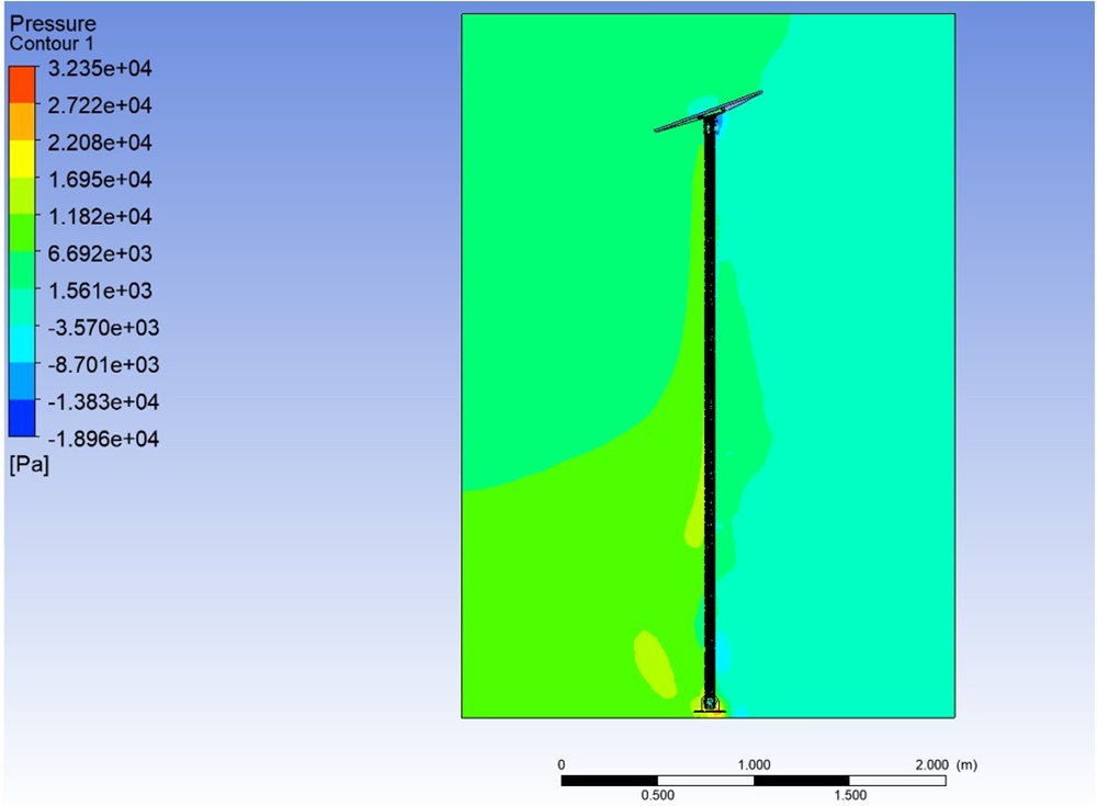
CFD pressure contour, 3,000 mm pole at 248 km/h. Maximum pressure 32,346 Pa, more than four times the short pole result. Source: Air Vision Systems Compliance Pack 2025
The engineering takeaway is straightforward. Keep the pole as short as your installation allows. Every additional metre of height puts the dish deeper into the free airstream and multiplies the structural load reaching the base of the adapter.
The Material: ADC12/A383 Cast Aluminium
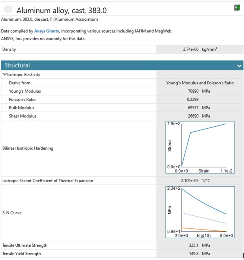
The bracket is cast from ADC12/A383 aluminium alloy, a die-cast aluminium grade widely used in structural and automotive applications where strength, corrosion resistance, and dimensional accuracy all matter.
From the engineering assessment, the material properties used in the simulation are:
- Tensile yield strength: 149.8 MPa
- Tensile ultimate strength: 325.1 MPa
- Young’s Modulus: 70,990 MPa
The bolts securing the bracket are carbon steel 1095, with a tensile yield strength of 1,042 MPa, roughly equivalent to a 12.9 grade bolt. That is a significant strength margin over the aluminium body, which means under load, the bracket is the component being assessed, not the fasteners.
Aluminium alloy was chosen deliberately. It offers a strong strength-to-weight ratio, resists corrosion in outdoor and coastal environments, and is well-suited to the precision demands of die casting. For a mount that lives outside year-round in all conditions, that combination matters.
Material distribution – ADC12/A383 aluminium alloy bracket body with carbon steel 1095 fasteners
The Result: A Factor of Safety of 2
With the CFD pressure load applied and the FEA fatigue simulation run to one billion cycles, the bracket returned a factor of safety (FOS) of approximately 2.
What does that mean in practical terms? A factor of safety of 2 means the bracket can withstand twice the applied fatigue load before reaching its structural limit. That load was already based on the most extreme wind speed ever recorded in Wellington. So the real-world safety margin built into this mount is substantial.
The Soderberg method used to calculate this result is deliberately conservative. It sits below the Goodman, Gerber and ASME Elliptical correction methods in terms of the stress it permits, meaning any of those alternative methods would have returned a higher factor of safety. The FOS of 2 is the most cautious number the analysis could produce, and it still clears the threshold with room to spare.
To put that margin in perspective, consider this: what would the factor of safety be if the bracket had only been tested against half that wind speed, say, 124 km/h?
The answer isn’t 4, it’s approximately 8. That’s because wind pressure doesn’t scale in a straight line with speed. It scales with the square of velocity. Cut the wind speed in half and the pressure load drops to one quarter of the original. At 124 km/h, the bracket would be seeing roughly 1,757 Pa instead of 7,030 Pa, and with the same structural capacity, the factor of safety jumps to around 8.
This is why using Wellington’s maximum recorded wind speed as the test basis matters so much. The vast majority of real-world installations, even in exposed rural, coastal or high-country locations, will never see 248 km/h. That means the effective safety margin in typical conditions is far greater than 2. The 248 km/h test case is the floor, not the ceiling.
For installers using the Starlink Gen 3 pole adapter wind rating as part of their hardware specification, and for property owners who want confidence that their Starlink dish will stay in place through whatever the weather throws at it, that is a result worth knowing about.
FEA fatigue analysis results – factor of safety approximately 2 using Soderberg mean-stress correction
Why AVS Mounts Are Engineering-Backed
• Wind speed tested: 248 km/h (Wellington maximum recorded)
• Peak pressure load: 7,030 Pa applied uniformly across the dish surface
• Fatigue cycles simulated: 1,000,000,000
• Fatigue method: Soderberg (most conservative available)
• Factor of safety: approximately 2
Most Starlink mounts come with no structural data at all. The AVS Gen 3 Clip-In Pole Adapter has been through a full CFD and FEA assessment, real simulation, real numbers, real wind conditions. That is not marketing. That is engineering. Browse the full range of AVS Starlink mounts to find the right solution for your installation.
Ready to fit a mount that’s been engineered for the worst?
The AVS Starlink Gen 3 Clip-In Pole Adapter is available now with fast shipping across New Zealand, Australia, Europe and the UK. Built from ADC12/A383 cast aluminium, tested to 248 km/h, and backed by a full CFD and FEA assessment.
Frequently Asked Questions
What does a factor of safety of 2 actually mean?
A factor of safety of 2 means the bracket can handle twice the load it was tested against before reaching its structural limit. Given the test used Wellington’s maximum recorded wind speed of 248 km/h, that is a significant real-world margin.
Is the clip-in design as strong as a traditional pole mount?
The clip-in mechanism is part of Starlink’s Gen 3 design. The AVS adapter works with that system and has been independently assessed via CFD and FEA simulation. The engineering data confirms it performs reliably under extreme wind loading.
How does pole length affect wind load on the bracket?
Significantly. A separate CFD comparison recorded a maximum pressure of 7,567 Pa on a 300 mm pole and 32,346 Pa on a 3,000 mm pole, both under the same 248 km/h wind input. The longer pole elevates the dish into faster, less sheltered airflow, and acts as a lever arm that amplifies the force reaching the base of the bracket. The engineering recommendation is to keep the pole as short as your installation allows.
What wind speeds is the bracket rated for?
The assessment used 248 km/h, the highest wind speed ever recorded in Wellington. Most installations across New Zealand, Australia, Europe and the UK will never see conditions anywhere near that level.
What material is the bracket made from and why does it matter?
The bracket is cast from ADC12/A383 aluminium alloy, a die-cast grade known for strength, corrosion resistance and dimensional accuracy. These are important qualities for a mount that lives outside year-round in all weather conditions.
Can installers get wholesale pricing on the Gen 3 Clip-In Pole Adapter?
Yes. AVS offers a wholesale programme for registered installers across New Zealand, Australia, Europe and the UK. Contact us to find out more.
The Starlink Gen 3 Pole Adapter Wind Rating: What the Engineering Shows Us
A clip-in mount is only as good as the engineering behind it. The AVS Starlink Gen 3 Clip-In Pole Adapter has been through a full computational assessment, CFD wind load simulation at 248 km/h, FEA structural analysis across one billion fatigue cycles, and a factor of safety result of approximately 2 using the most conservative calculation method available. That’s the kind of data most mount manufacturers simply do not provide.
Whether you’re a homeowner in a high-wind location, a farmer putting Starlink on a remote outbuilding, or an installer specifying hardware for clients across New Zealand, Australia, Europe or the UK, this is a mount you can spec with confidence.
View the AVS Starlink Gen 3 Clip-In Pole Adapter
Want to size your cable run to go with it? Use the AVS Smart Cable Calculator to get the right AWG for your install length.