Based on engineering analysis commissioned by Air Vision Systems | NZ, AU and Global
When Cyclone Chido made landfall over Mayotte in December 2024, questions about Starlink Gen 3 mount wind performance became very real, very fast. It was the most powerful storm to hit the French Indian Ocean territory in nearly 90 years. Wind speeds exceeded 220 km/h. Infrastructure was devastated. For the people on that island, and thousands like them across cyclone and hurricane-prone regions worldwide, reliable communications during and after a major storm is not a luxury. It is a lifeline.
The AVS Starlink Generation 3 Mount was designed with exactly that in mind. It is a white powder-coated marine-grade aluminium mount with a high-quality polycarbonate cover, built to protect and secure the Starlink Gen 3 dish in permanent and semi-permanent installations on rooftops, boats, caravans, RVs, and off-road vehicles.
Our engineering brief had two benchmarks: the highest wind speed recorded in Wellington, New Zealand over the last 100 years at 248 km/h, and the threshold for a Category 5 hurricane at 252 km/h. We then commissioned a full Computational Fluid Dynamics (CFD) and Finite Element Analysis (FEA) simulation to prove the design could meet both. This post walks you through what was tested, what the numbers mean, and what it tells you about how your Starlink will perform when the weather turns truly serious.
What We Tested and Why
The AVS Starlink Generation 3 Mount is designed for installations where the Starlink needs to stay put and keep working regardless of conditions. That includes exposed rooftops in Wellington, coastal properties across New Zealand and Australia, boats and yachts in cyclone-prone waters, and remote sites where a failed mount means no communications at all. But building something solid is not enough on its own. We wanted hard engineering data to back up every claim.
To get that, we commissioned a two-stage engineering simulation. First, a CFD analysis to calculate the pressure that Category 5 hurricane winds would place on the cover surface. Second, an FEA to test whether the structure could handle that pressure repeatedly, across a billion load cycles. The goal was simple: find any weak points before a storm does. Understanding the Starlink Gen 3 mount wind load limits under real-world conditions was the starting point for the entire analysis.
How Wind Load Was Calculated
The starting point for the wind load calculation was real-world data. Wellington, New Zealand holds one of the highest recorded wind speeds of any city on earth, with gusts regularly exceeding 150 km/h and a recorded peak of 248 km/h. That recorded peak became the baseline for our engineering brief. From there, the simulation was extrapolated to 252 km/h, the sustained wind speed threshold for a Category 5 hurricane on the Saffir-Simpson scale.
A CFD simulation was run with airflow directed perpendicularly onto the full face of the dish cover, the worst-case scenario for wind loading. This identified the stagnation point at the centre of the cover, where oncoming airflow velocity drops to zero and pressure peaks at its highest. That maximum pressure figure was then applied across the entire cover surface for the structural analysis, rather than just at the stagnation point. This is a deliberately conservative approach. In reality, pressure is not uniform across the whole face, but testing as if it were ensures the results account for worst-case conditions.
If the AVS Starlink Gen 3 Mount wind rating holds at 252 km/h, it holds in Wellington. That is not a marketing claim. It is the output of the same engineering methodology used in aerospace, civil, and marine structural analysis.
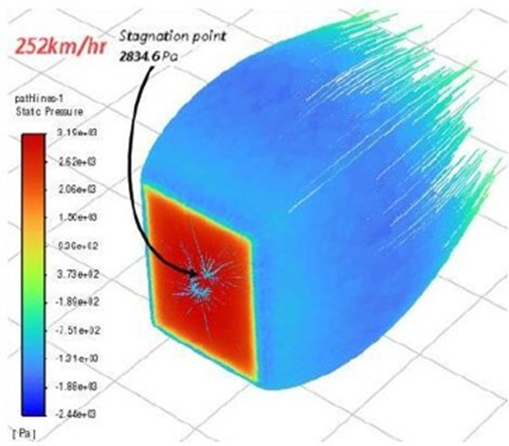
Figure 1: CFD pressure simulation at 252 km/h. Stagnation point at dish centre peaks at 2,834 Pa. Source: Air Vision Systems Compliance Pack 2025
What the Structural Analysis Revealed
Once the wind pressure load was established, it was applied to a full structural model of the mount assembly in the FEA simulation. To find the most critical stress points, the model was run under fully reversed fatigue loading, meaning the load cycles repeatedly in both directions, which is the harshest possible fatigue scenario for any structure.
The analysis used the Soderberg method to calculate the results. This is widely regarded as the most conservative approach in fatigue engineering, factoring in both the alternating stress and the mean stress to produce a rigorous assessment of long-term durability.
The results were clear. The AVS Starlink Gen 3 mount wind performance passed comfortably. The minimum fatigue safety factor recorded across the assembly was above 7, tested to one billion load cycles. At Category 5 hurricane wind speeds, the structure has more than seven times the strength required to avoid fatigue failure, even under continuous repeated loading.
The highest stress in the assembly was concentrated in the aluminium base bracket, specifically in the spring-action holding sections that flex slightly under load and absorb stress away from the bolts and the polycarbonate cover. This is exactly the behaviour you want to see. The design channels stress into the areas built to handle it, protecting the rest of the assembly.
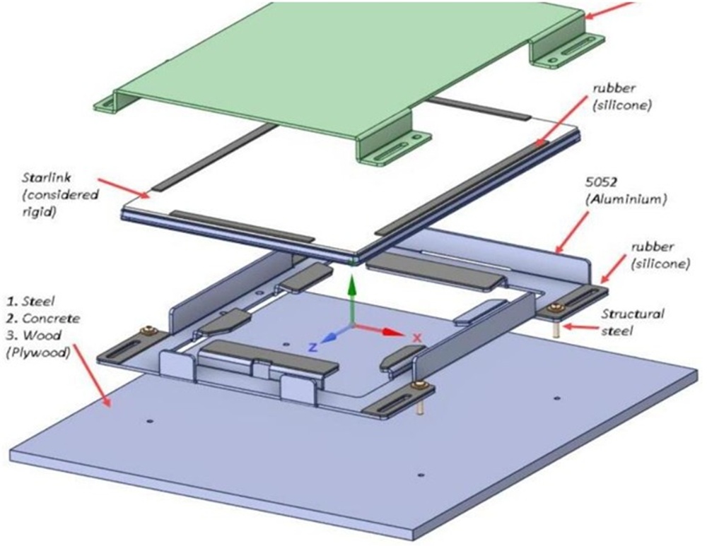
Figure 2: Exploded assembly view showing material distribution. Polycarbonate cover, silicone pads, 5052 aluminium base and structural steel fixings. Source: Air Vision Systems Compliance Pack 2025
Engineering Note
The CFD simulation used an airflow velocity of 252 km/h, the Category 5 hurricane threshold, directed perpendicularly onto the full dish cover surface. This is the worst-case loading scenario. The maximum stagnation pressure of 2,834 Pa was then applied uniformly across the entire cover face for the structural analysis, a deliberately conservative approach that exceeds real-world pressure distribution. The fatigue analysis used the Soderberg method, the most conservative calculation standard in fatigue engineering, and tested to one billion fully reversed load cycles. Minimum safety factor recorded: above 7 across all three foundation types tested.
Read the redacted engineering report summary here.
The full unredacted report is available under NDA to distributors, wholesale partners, Starlink installers, commercial operators, infrastructure and telecommunications providers, and insurers or risk assessors with a legitimate requirement. Contact us to request access.
Does the Mounting Surface Matter?
One of the most practical questions for anyone assessing Starlink Gen 3 mount wind resistance is what surface it is going onto. A rooftop deck, a concrete pad, a steel frame, a wooden structure. The surface varies enormously depending on the installation. So we tested all three of the most common real-world foundation types: plywood, steel, and concrete.
The short answer is that all three pass. Comfortably.
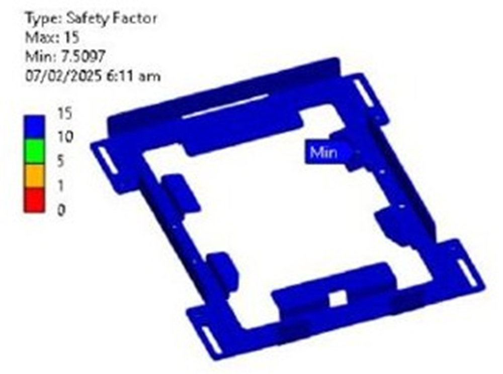
Figure 3: Fatigue safety factor results. Plywood foundation. Minimum FOS: 7.5 across 1 billion fully reversed load cycles at Category 5 wind pressure. Source: Air Vision Systems Compliance Pack 2025
The plywood foundation returned a minimum fatigue safety factor of above 7.5. Steel came in above 10. Concrete returned a minimum safety factor of above 7.3. Across all three cases the stress distribution remained even, the polycarbonate cover deflected no more than 5.7 mm under full Category 5 load, a level that has no impact on the structural integrity of the assembly, and the aluminium bracket tips moved less than 1 mm.
Whether the AVS Starlink Gen 3 Mount is bolted to a timber roof, a steel frame, or a concrete surface, the engineering outcome is the same. The mount holds. The Starlink stays connected. That applies equally whether the site is in a Pacific cyclone zone, an Australian coastal property, or on an exposed Wellington rooftop.
What a Safety Factor of 7+ Actually Means
Safety factor is an engineering term that does not always land well outside technical circles, so it is worth explaining in plain language.
A safety factor of 1 means a structure is right at its limit. Any additional load and it fails. A safety factor of 2 means it can handle twice the design load before failure. A safety factor of 7 means the structure would need to experience seven times the applied load before reaching its fatigue limit. In this case, that applied load is already Category 5 hurricane wind pressure. So the mount would need to be subjected to the equivalent of seven Category 5 hurricanes simultaneously before the engineering model predicts fatigue failure.
For context, structural engineers typically consider a safety factor of 2 to 3 acceptable for most applications. Safety factors above 5 are considered highly conservative. The AVS Gen 3 Mount exceeds that benchmark across every foundation type tested, using the most conservative fatigue calculation method available.
This matters because fatigue failure is cumulative. It is not just about surviving one storm. It is about what happens after the tenth storm, or the fiftieth. Engineering to one billion fully reversed load cycles at Category 5 pressure, with a safety factor above 7, means the AVS Gen 3 Mount is built for a working lifetime in harsh conditions, not just a single weather event. For anyone on an exposed site in New Zealand or Australia, or in a cyclone or hurricane-prone region anywhere in the world, that distinction matters.
Built for the worst weather on earth. Ready for yours.
The AVS Starlink Generation 3 Mount is engineered and tested to Category 5 hurricane wind speeds, not as a marketing claim, but as a verified engineering outcome. If you are in a cyclone zone, on the water, in a remote location, or simply somewhere the weather does not play nice, this is the mount built to keep your Starlink connected when it matters most.
View the AVS Starlink Gen 3 Mount
Frequently Asked Questions
Will my Starlink mount stay on in high winds?
That depends entirely on the mount. The AVS Starlink Gen 3 Mount was tested to 252 km/h, the Category 5 hurricane threshold, under fatigue loading across one billion cycles. At those wind speeds it returned a minimum safety factor of above 7. If a mount has no engineering data behind it, there is no way to know how it will perform in strong wind or storm conditions. For exposed sites, coastal properties, or anywhere that experiences high winds, the Starlink Gen 3 mount wind specification matters.
What wind speed is the AVS Gen 3 Mount tested to?
The AVS Gen 3 Mount was tested to 252 km/h, the sustained wind speed threshold for a Category 5 hurricane on the Saffir-Simpson scale. That figure was also chosen because it exceeds the highest wind speed ever recorded in Wellington, New Zealand at 248 km/h, making it directly relevant to exposed NZ and Australian sites as well as cyclone and hurricane-prone regions worldwide.
How does a safety factor of 7+ compare to standard engineering requirements?
Structural engineers typically consider a safety factor of 2 to 3 acceptable for most applications, and anything above 5 is regarded as highly conservative. The AVS Gen 3 Mount returned a minimum safety factor of above 7 across all foundation types tested, using the most conservative fatigue calculation method available. That means the mount has more than seven times the strength required to avoid fatigue failure at Category 5 wind loading.
Is the AVS Gen 3 Mount suitable for marine and boat installs in cyclone-prone regions?
Yes. The mount is constructed from white powder-coated marine-grade aluminium specifically to handle harsh marine environments. Combined with the Category 5 wind load testing and a safety factor of above 7 across all foundation types, it is well suited to boat, yacht, and coastal installs in cyclone and hurricane-prone regions worldwide.
Will the polycarbonate cover affect my Starlink signal?
No. The polycarbonate cover is fully signal-transparent and has no impact on Starlink performance. You get full weather protection without any compromise to your connection.
Where can I read the full engineering report?
A redacted summary of the engineering report is available to read here. The full unredacted report is available under NDA to distributors, wholesale partners, Starlink installers, commercial operators, infrastructure and telecommunications providers, and insurers or risk assessors with a legitimate requirement. Contact us to request access.
What the Engineering Tells Us
Most mounting products are designed to look good in product photos. The AVS Starlink Generation 3 Mount was designed to survive Cyclone Chido.
That meant starting with real-world data, the highest wind speeds recorded in Wellington over the last 100 years, and engineering upward from there to Category 5 hurricane conditions. It meant commissioning independent CFD and FEA structural simulations, testing to one billion fatigue cycles, using the most conservative calculation methods available, and validating the results across three different foundation types. It meant not stopping until the numbers said the mount would hold. The result is a safety factor of above 7 at 252 km/h. On plywood, steel, and concrete. With the polycarbonate cover intact and signal-transparent throughout.
If you are running Starlink somewhere the weather can turn serious, a cyclone zone, a remote farm, a boat, a coastal property, or anywhere in Wellington, the AVS Gen 3 Mount is the only Starlink mount with the engineering data to back up every claim we make.
View the AVS Starlink Generation 3 Mount
Want to dig into the numbers yourself? The redacted engineering report summary is available to read here.