Based on engineering analysis commissioned by Air Vision Systems | NZ, AU and Global
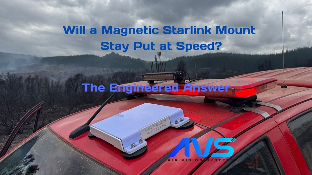
A magnetic Starlink mount is the cleanest way to fit a Starlink Mini on a vehicle roof without drilling holes. Fast to install, no permanent modifications, and no damage to your paintwork. But the obvious question is: will it actually hold?
It is a fair concern. A magnetic mount on a moving vehicle is dealing with wind pressure, road vibration, and changing speeds, all at the same time. The wrong setup does not just underperform, it fails. And with a Starlink dish on the line, that is not a risk worth taking.
At Air Vision Systems, we ran the numbers. Using ANSYS finite element analysis software, we simulated both a 4-magnet and an 8-magnet configuration under conservative real-world conditions, including a worst-case wet roof friction coefficient and wind loads equivalent to 178 km/h. One configuration passed. One did not. This post covers exactly what the engineering showed.
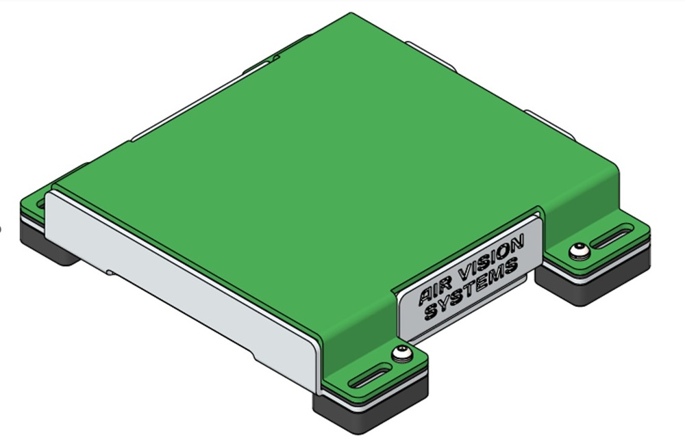
AVS Starlink Mini Magnetic Mount – Underneath View (8-Magnet Configuration)
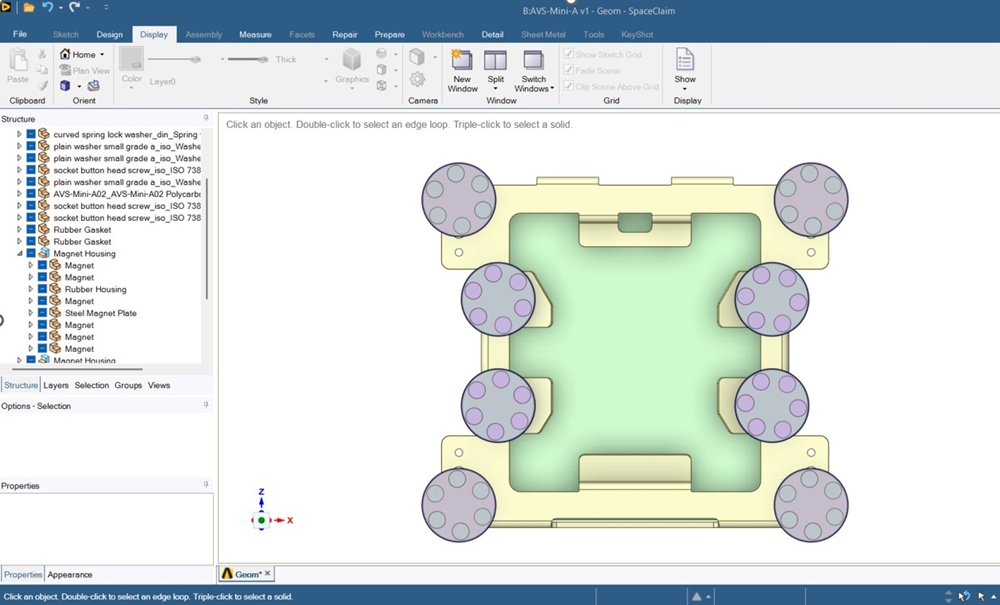
AVS Starlink Mini Magnetic Mount – Top View with Magnets
How a Magnetic Mount Works on a Vehicle Roof
The AVS magnetic Starlink mount uses discrete magnetic contact points to hold the bracket against the vehicle roof. The magnets pull down against the steel surface, generating a normal force. That normal force, combined with the friction between the rubber-encased magnet housings and the roof, is what resists the mount sliding sideways under wind load.
This means there are two things that matter: how much downward force the magnets generate, and how grippy the contact surface is. Get either of those wrong, too few magnets, or a slippery roof, and the mount slides.
The engineering assessment modelled exactly this scenario, using ANSYS Mechanical to simulate the full assembly under aerodynamic loading. Each HNDH-66 magnetic unit has a rated breakaway force of 22 kg (216 N). To account for real-world variables like paint thickness, surface contamination, rain and vibration, a conservative utilisation factor of 0.70 was applied, bringing the allowable design load down to 150 N per magnet.
The Test Conditions: Wind Loads and Worst-Case Friction
Wellington, New Zealand is one of the windiest cities in the world, and it is the benchmark AVS uses for conservative wind load testing. For this assessment, a base wind speed of 45 m/s was used to calculate dynamic pressure, with a further engineering margin applied to account for gusts, flow acceleration and vehicle turbulence. The final applied pressure used in the simulation was 1,500 Pa, equivalent to a vehicle speed of approximately 178 km/h.
For friction, the analysis used a coefficient of 0.20. That is a worst-case figure representing the most slippery real-world conditions you are likely to encounter, including a wet roof, polished paint, or a surface with dust, road grime or wax. Most real-world conditions will produce higher friction than this, making the assessment deliberately conservative.
The governing failure mode identified in the report is sliding, not material failure, not bolt failure, not roof panel failure. The mount either holds through friction, or it does not. Everything in the analysis is built around that single question.
Why 4 Magnets Fail
With four magnets, the total allowable normal force is 4 x 150 N = 600 N. Apply the worst-case friction coefficient of 0.20 and the maximum frictional resistance the mount can generate is just 120 N.
The ANSYS simulation confirmed the problem. Under the applied 1,500 Pa pressure load, each magnet was seeing a reaction force of approximately 220 N, well above the 150 N allowable design load, and exceeding even the rated 216 N breakaway force. Every magnet in the 4-magnet configuration was being asked to do more than it was designed to handle.
The simulation showed what happens next: the contact pattern transitions from full contact to partial contact, and then to near separation. The magnets begin losing grip on the roof surface. Once that starts, load redistributes onto the remaining contact points, accelerating the problem. The 4-magnet configuration does not just underperform. It trends toward sliding failure under the stated conditions.
The verdict from the engineering assessment is unambiguous: the 4-magnet configuration fails.
4-Magnet Configuration – Isometric View
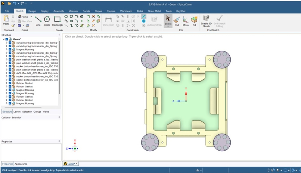
4-Magnet Configuration – Plan View
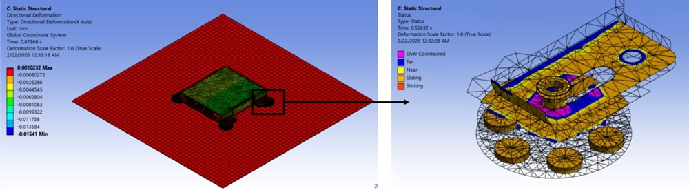
ANSYS simulation result for 4-magnet configuration – contact loss and sliding behaviour
Why 8 Magnets Pass
Doubling the magnets does not simply double the holding capacity. It changes the behaviour of the entire system. With eight magnets, the load distributes across more contact points, reducing the demand on any individual magnet and keeping the assembly in stable contact with the roof.
The ANSYS results for the 8-magnet configuration show how load sharing actually plays out in practice. The four corner magnets carry the majority of the load at approximately 220 N each, while the four mid-side magnets carry significantly less at around 12 N each. This non-uniform distribution is expected. It is a product of frame stiffness and contact geometry, but it does not undermine the result. What matters is the total effective normal force across the system.
Adding that up: (4 x 220) + (4 x 12) = 928 N total effective normal force. At a friction coefficient of 0.20, that produces a frictional resistance of 185 N, comfortably above the applied shear load from the 1,500 Pa wind pressure.
The simulation confirmed full contact retention across all eight magnets, with no sliding and no lift-off observed. Individual magnet reactions remained well below the physical breakaway capacity of 216 N. The 8-magnet configuration passes.
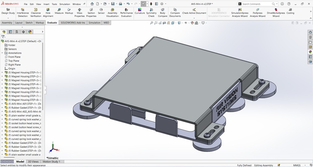
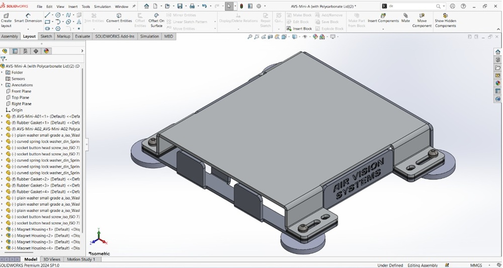
8-Magnet Configuration – Isometric View
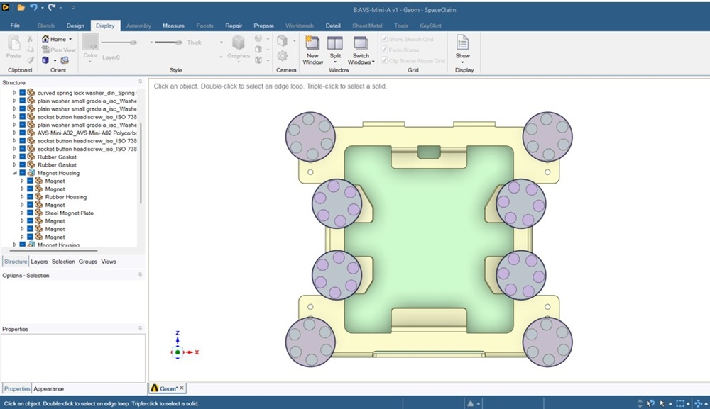
8-Magnet Configuration – Plan View
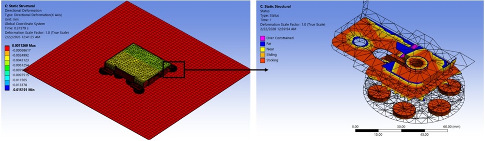
ANSYS simulation result for 8-magnet configuration – full contact retention confirmed
What This Means in the Real World
The engineering result is clear, but it is worth translating into what it actually means for overlanders, campervan travellers, caravan owners and boaties using this mount day to day.
The test conditions were deliberately punishing. A friction coefficient of 0.20 represents a wet, contaminated, or freshly waxed roof, not ideal conditions by any measure. The 1,500 Pa pressure load is equivalent to 178 km/h, with a dynamic margin already built in for gusts and road buffeting. Most real-world driving situations will sit well below both of those figures, which means the effective safety margin for a magnetic Starlink mount in typical use is considerably greater.
A few practical points worth noting from the report. The mount is assessed on a flat, uncoated steel roof. Aluminium and composite roofs have no ferromagnetic properties, meaning the magnets will not grip at all. This mount is only suitable for steel roof surfaces.
Most vehicle roofs are curved, not flat. A curved surface reduces the effective contact area between the magnet housing and the roof, which will reduce both magnetic pull and frictional resistance compared to the flat-surface results in this assessment. The more pronounced the curve, the greater that reduction. Surface condition also matters: ceramic coatings, thick wax layers, or road grime all reduce effective friction further. For best performance, fit the mount to a clean, dry, flat or low-curvature steel surface.
The bottom line is straightforward. Four magnets were tested and failed under conservative conditions. Eight magnets were tested and passed. That is the engineering basis for the AVS magnetic mount design, and it is why two sets of magnets are required for the approved 8-magnet configuration.
The Engineering Case for 8 Magnets
Wind pressure tested: 1,500 Pa (equivalent to approximately 178 km/h)
Friction coefficient used: 0.20 (worst-case wet or contaminated roof)
Roof type assessed: flat, uncoated steel
4-magnet configuration: 120 N frictional resistance — FAIL
8-magnet configuration: 185 N frictional resistance — PASS
Note: this mount requires a steel roof surface. Aluminium and composite roofs have no magnetic attraction. The magnets are sold separately.
The AVS High Strength Mounting Magnets (Set of 4) are available separately – two sets are required for the approved 8-magnet configuration.
Looking for a No-Drill Starlink Mount Backed by Engineering?
The AVS Starlink Mini Mount is a compact, marine-grade bracket designed for a range of installs, including the 8-magnet configuration that passed the engineering assessment. Pair it with two sets of AVS High Strength Mounting Magnets for the approved 8-magnet setup.
View the AVS Starlink Mini Mount
View the High Strength Mounting Magnets (Set of 4)
Frequently Asked Questions
Will this magnetic mount work on any vehicle roof?
Only on steel roofs. Aluminium and composite roofs have no ferromagnetic properties, meaning the magnets will not grip at all. Most modern steel-roofed vehicles are compatible, but always check your roof material before purchasing.
Do I need two sets of magnets for the 8-magnet configuration?
Yes. The AVS High Strength Mounting Magnets are sold in sets of 4. The engineering assessment confirmed that 4 magnets fail under conservative test conditions, so two sets, giving you 8 magnets total, are required for the approved configuration.
Does the curve of my vehicle roof affect how well the mount holds?
Yes, and it is worth factoring in. The engineering assessment was conducted on a flat steel surface. A curved roof reduces the effective contact area between the magnet housings and the roof, which reduces both magnetic pull and frictional resistance. The more pronounced the curve, the greater that reduction.
What speed was the mount tested to?
The simulation applied a pressure load of 1,500 Pa, equivalent to approximately 178 km/h, with a dynamic margin already built in for gusts and road buffeting. This is a conservative test condition. Most real-world driving will sit well below this figure.
Can I use this mount on a boat?
The AVS Starlink Mini Mount is a marine-grade bracket, making it well suited to boat installs. For magnetic mounting on a vessel, the same steel surface requirement applies. Check that the mounting surface is steel before fitting.
What the Engineering Tells Us
The engineering case is clear. Under conservative test conditions, a worst-case friction coefficient of 0.20, a flat uncoated steel surface, and a wind pressure load equivalent to 178 km/h, four magnets generate insufficient frictional resistance and fail. Eight magnets distribute the load across more contact points, generate 185 N of frictional resistance, and pass.
That is not a marginal result. It is a FAIL versus a PASS, and the difference comes down to the number of contact points holding the mount to the roof. The AVS magnetic mount design is built around that engineering outcome.
Whether you are heading off-road, travelling in a campervan, towing a caravan, or fitting Starlink to a boat, the AVS Starlink Mini Mount paired with two sets of High Strength Mounting Magnets gives you a no-drill setup that has been put through the numbers, not just put on the shelf.
View the AVS Starlink Mini Mount
View the High Strength Mounting Magnets (Set of 4)
Want to confirm the right cable for your install? Use the AVS Smart Cable Calculator to get the right AWG for your run length.